Centrifugal clutch assembly with dedicated maneuvering mode

a technology of centrifugal clutch and dedicated maneuvering mode, which is applied in the direction of mechanical equipment, instruments, transportation and packaging, etc., can solve problems such as engine speed problems, and achieve the effect of improving vehicle speed control

Inactive Publication Date: 2008-03-04
MERITOR TRANSMISSION CORP
View PDF32 Cites 6 Cited by
  • Summary
  • Abstract
  • Description
  • Claims
  • Application Information

AI Technical Summary

Benefits of technology

[0008]In one disclosed embodiment, clutch torque is controlled by engine fueling commands. The control unit monitors the maneuvering mode switch and the accelerator pedal position to determine an appropriate fueling command. When the vehicle is operating in the low speed maneuvering mode, the engine speed in the range of rising clutch torque is controlled over a greater range of accelerator pedal movement than in a normal vehicle-operating mode. This significantly improves clutch torque control and vehicle acceleration and vehicle speed variation at low-speed operations. Because transmitted torque of a slipping centrifugal clutch is only dependent on engine speed, only the engine speed has to be controlled by adjusting fuel injection in order to get a desired clutch torque a desired vehicle acceleration during clutch slippage. After clutch lockup, engine speed is proportional to vehicle speed.

Problems solved by technology

As clutch torque rises, there are two main problems.
One problem concerns engine speed issues at slow accelerator pedal actuation and the other problem concerns engine speed issues at quick accelerator pedal actuation.
Specifically, the first problem involves an engine speed characteristic versus accelerator pedal travel at slow accelerator pedal movement.

Method used


Image

  • Centrifugal clutch assembly with dedicated maneuvering mode
  • Centrifugal clutch assembly with dedicated maneuvering mode
  • Centrifugal clutch assembly with dedicated maneuvering mode

Examples


Embodiment Construction

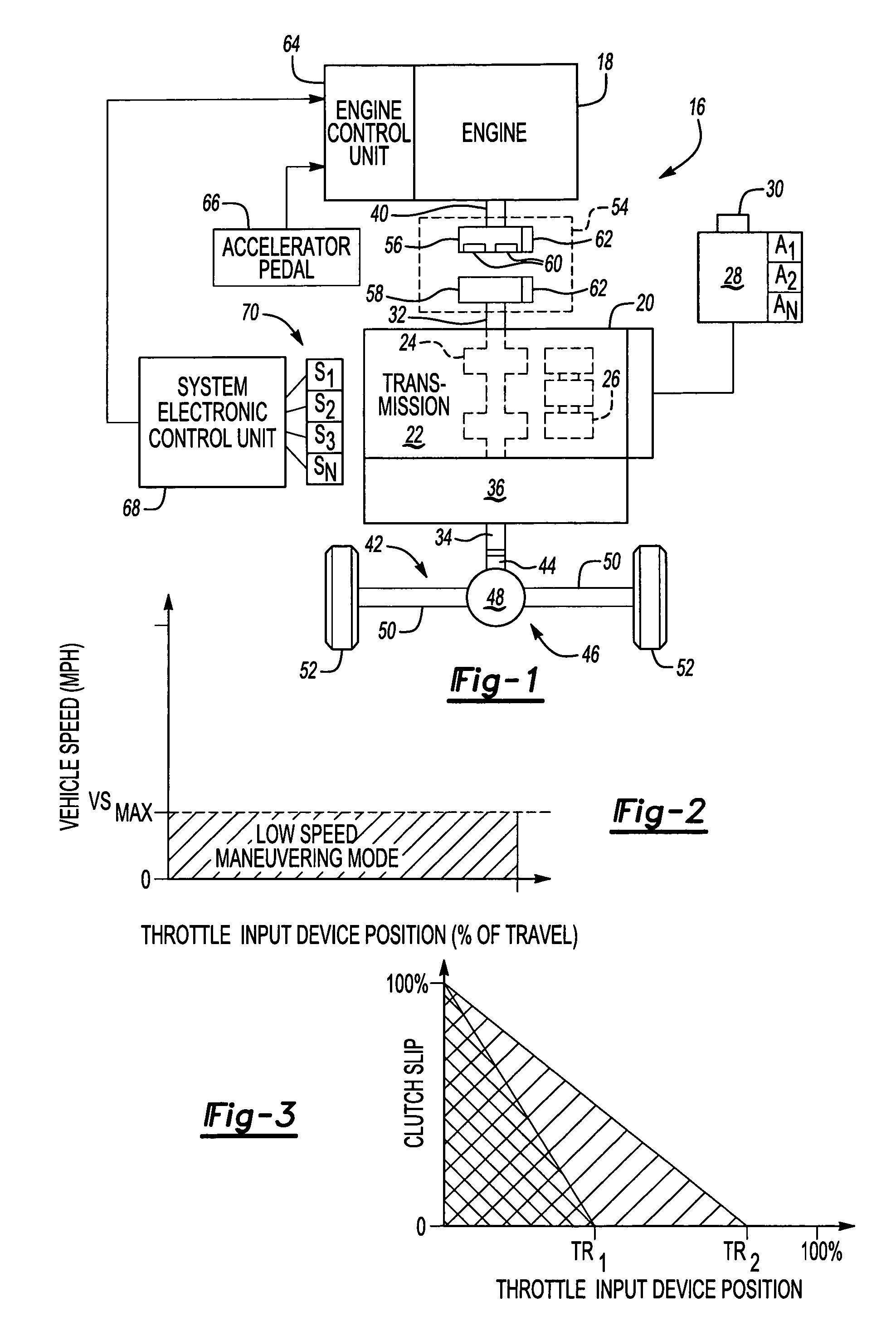
[0018]FIG. 1 diagrammatically illustrates a power train system 16 including an engine 18 and a transmission 20. The transmission 20 includes a main gear box 22 that has a plurality of gear members 24 and 26. In the illustrated embodiment, a gear selection device 28 includes an input 30 that is manually or automatically controlled to selectively engage one of the gear members 24 and 26 to achieve a desired gear ratio between a transmission input shaft 32 and a transmission output shaft 34. An operator manipulates or activates the input 30 to select between a plurality of operating modes A1, A2 . . . An, which includes at least a low-speed maneuvering mode. The low-speed maneuvering mode is selected for low speed operations such as coupling a truck and trailer together, or positioning a truck and / or trailer relative to a loading dock area, for example.

[0019]The transmission 20 can include an auxiliary transmission 36 such as a splitter gear assembly or a range gearbox to provide addit...


PUM


Abstract

A vehicle power train system includes an engine, a transmission, and a centrifugal clutch assembly that selectively couples an engine output shaft to a transmission input shaft in response to an operator input. An operator selects a desired vehicle-operating mode by actuating a shift lever or shift switch from a gear selection device. The gear selection device indicates many different operating modes and includes a low-speed maneuvering mode that is selected for low-speed operations such as coupling a truck to a trailer, or positioning a truck and / or trailer in relation to a loading dock area. Once the low-speed maneuvering mode is selected, a control unit controls at least one of engine speed and engine torque to indirectly effect clutch slippage, which results in improved vehicle speed control at low-speed operations.

Description

BACKGROUND OF THE INVENTION[0001]This application generally relates to a vehicle clutch assembly and associated engine control system that more precisely controls vehicle speed during low-speed vehicle operations. More particularly, this invention relates to an engine control system that indirectly effects clutch slippage for a centrifugal clutch assembly in response to selection of a dedicated maneuvering mode for low-speed vehicle operation.[0002]Ideally, transmissions include a deep reduction or low-speed creep ratio that allows the vehicle to operate at very low-speeds. This deep reduction is not utilized during a significant portion of the overall operating time of the vehicle. Thus, the inclusion of structure within the transmission to provide the deep reduction significantly increases the cost of the transmission.[0003]One solution has eliminated this deep reduction from the transmission by providing for a simulated creep ratio. In this creep control mode, a wide range of acc...

Claims


Application Information

Patent Timeline
Patent Type & Authority Patents(United States)
IPC IPC(8): B60W10/04
CPCB60K31/04B60W2540/10Y10T477/6403B60W2710/0616Y10T477/78B60W2710/025
Inventor RONGE, LUDGERALLEN, JR., CHARLES E.STURMER, WINFRIEDHEINZELMANN, KARL-FRITZDEVORE, JAMES H.DREIER, LOREN C.SAYMAN, ROBERT A.MUETZEL, RONALD P.ABUSAMRA, MUNEER
Owner MERITOR TRANSMISSION CORP
Why Eureka
Try Eureka