
Humeral stem with anatomical location of taper access for fixation of humeral head

a humeral stem and taper access technology, applied in the field of apparatus and method of shoulder arthroplasty, can solve the problems of inability to provide proper joint articulation, lack of proper spacing of the head radius, and lack of prior art humeral components used in shoulder arthroplasty

Inactive Publication Date: 2008-03-04
BIOMET MFG CORP
View PDF24 Cites 65 Cited by
  • Summary
  • Abstract
  • Description
  • Claims
  • Application Information

AI Technical Summary

Benefits of technology

The present invention is about an apparatus and method for shoulder arthroplasty. It involves using a humeral component and other surgical components for shoulder replacement. The humeral component is designed to be implanted into the humerus and engaged with a glenoid component. The invention also includes a kit with different stem diameters and humeral heads with varying radiuses. The stems have a hole at a fixed distance from the proximal end, and the heads can be mated with the stems so that they overlap the center line less than a predetermined amount. The invention also includes a modular prosthesis for implant into a humerus with a proximal head coupling device that can accept heads with an articulating surface. The heads are offset a predetermined distance from the coupling device. Overall, the invention provides a more versatile and customizable solution for shoulder replacement surgery.

Problems solved by technology

However, the current prior art humeral components along with the associated surgical components and instruments utilized during shoulder arthroplasty suffer from many disadvantages.
However, such existing stemmed humeral components also exhibit several disadvantages.
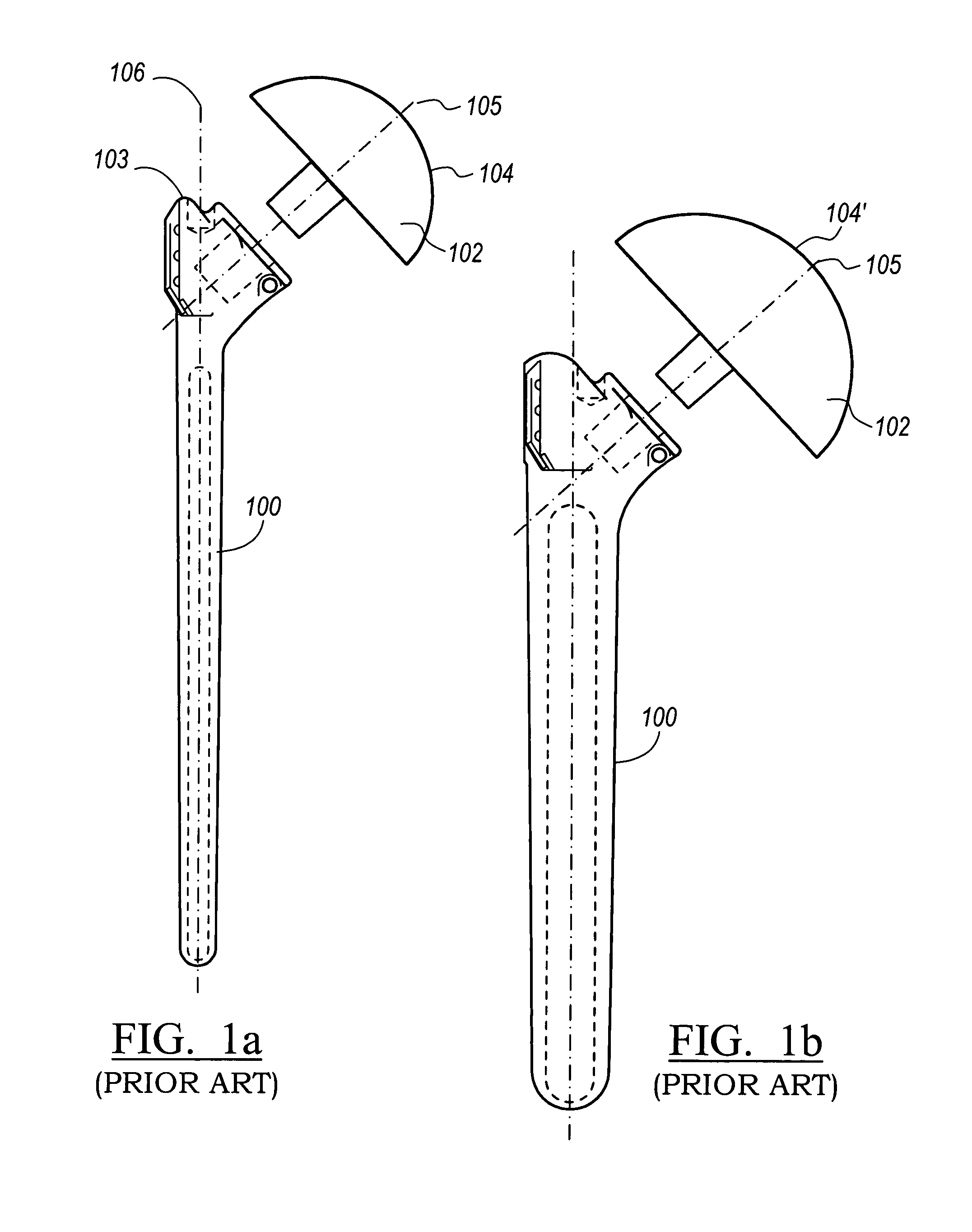
While the hemispherical radius of the head can be adjusted to compensate for differences in the stem size, use of such an adjusted head radius does not always provide proper spacing and allow proper joint articulation since the articulation axis of the head does not change with the change in head size.
To overcome this, a myriad of designs offer heads having offset pegs and sleeves, thus increasing the complexity of the surgery.
This is an undesirable condition which leads to improper joint kinematics.

Method used


Image

  • Humeral stem with anatomical location of taper access for fixation of humeral head
  • Humeral stem with anatomical location of taper access for fixation of humeral head
  • Humeral stem with anatomical location of taper access for fixation of humeral head

Examples


Embodiment Construction

[0023]The following description of the preferred embodiments concerning an apparatus and method for shoulder arthroplasty is merely exemplary in nature and is in no way intended to limit the invention, its application, or uses. Moreover, while the present invention is directed to a shoulder joint, the present invention may be employed in other joints as well, such as a hip joint.

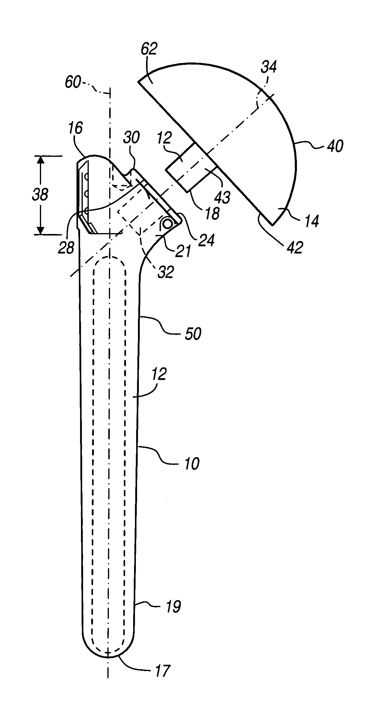
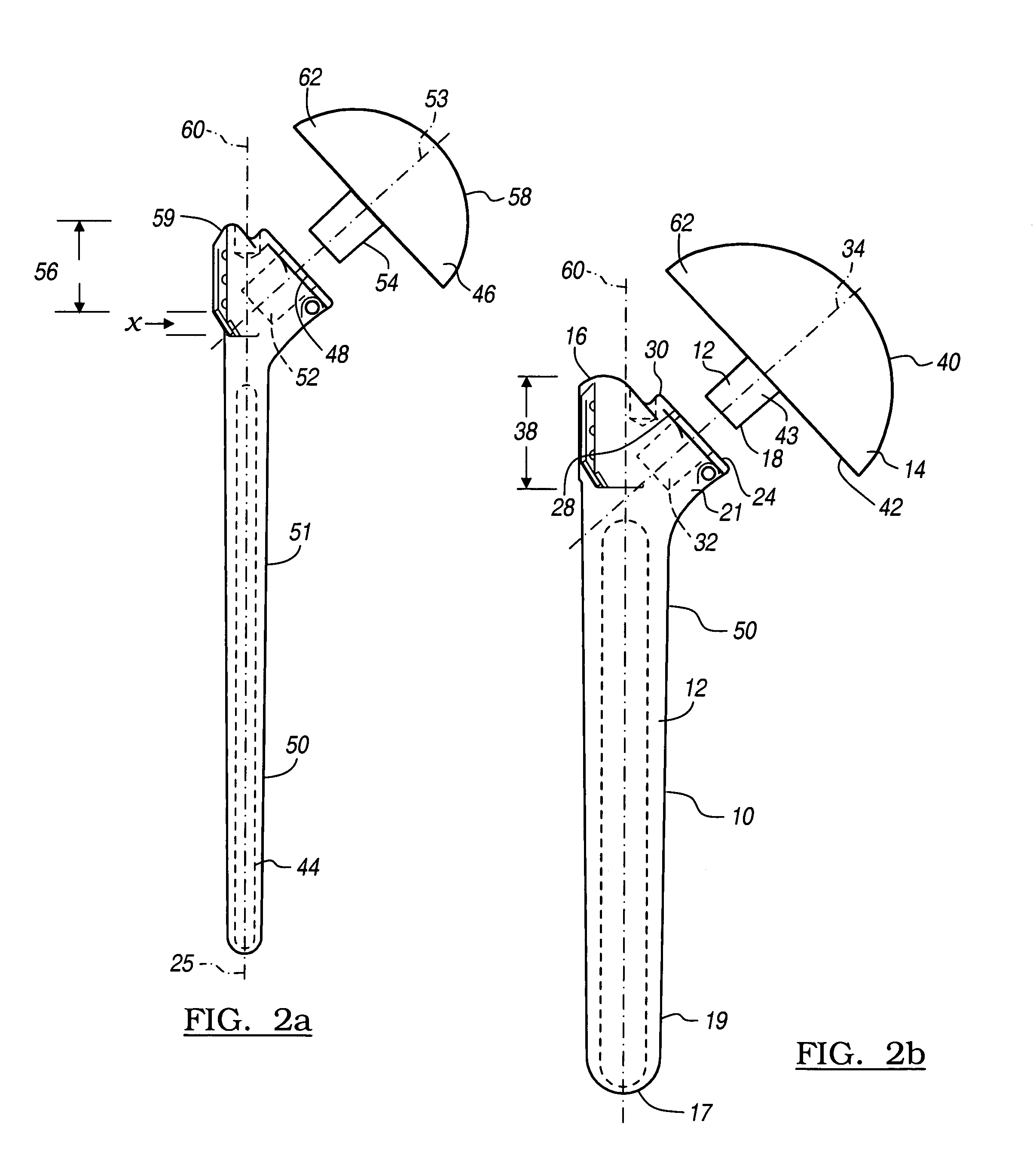
[0024]With reference to FIGS. 2a-4 represent a kit which contains a pair of modular humeral prosthesis 10 and 50 are shown. Referring now to the first prosthesis 10, which has a stem portion 12, and humeral head 14. When assembled, the humeral head 14 is joined to the stem 12 by means of a Morse Taper 18. Components of the Morse Taper 18 are formed on the stem 12 and the head 14. Disposed between a proximal end 16 and a distal end 17 of the stem 12 is a tapered shaft 19 having a first cross-sectional diameter. Disposed on the proximal end 16 of the stem portion 12 is a coupling portion 21 having a platform 2...


PUM


Abstract

Disclosed is a kit having a set of humeral components used in partial and total joint replacement surgeries. The set of humeral components has a plurality of stems having varying stem diameters and a set of humeral heads having hemispheric surfaces with varying radiuses. Each stem defines a platform having a hole which is a fixed distance from the proximal end of the stem. The distance of the hole from the proximal end of the stem is a function of the stem diameter.

Description

BACKGROUND OF THE INVENTION[0001]1. Field of the Invention[0002]This invention relates generally to an apparatus and method for shoulder arthroplasty and, more particularly, to a humeral component and other associated surgical components and instruments for use in shoulder arthroplasty.[0003]2. Discussion of the Related Art[0004]A natural shoulder joint may undergo degenerative changes due to a variety of etiologies. When these degenerative changes become so far advanced and irreversible, it may ultimately become necessary to replace a natural shoulder joint with a prosthetic shoulder joint. When implantation of such a shoulder joint prosthesis becomes necessary, the natural head portion of the humerus is resected and a cavity is created in the intramedullary canal of the host humerus for accepting a humeral component. The humeral component includes a head portion used to replace the natural head of the humerus. Once the humeral stem component has been implanted, the humeral head is...

Claims


Application Information

Patent Timeline
Patent Type & Authority Patents(United States)
IPC IPC(8): A61F2/40A61F2/00A61F2/30
CPCA61F2/4014A61F2/4059A61F2002/30245A61F2002/30332A61F2002/30405A61F2002/30616A61F2002/4033A61F2002/4037A61F2002/4044A61F2002/4051A61F2220/0025A61F2220/0033A61F2230/0071A61F2310/00017A61F2310/00023A61F2310/00029A61F2310/00179
Inventor STONE, KEVIN T.CORDARO, NICHOLAS M.
Owner BIOMET MFG CORP
Learn More