Wavelength converting optical system, laser light source, exposure apparatus, device for inspecting object of inspection, and polymer crystal working apparatus

a wavelength conversion and optical system technology, applied in the direction of light demodulation, instruments, laser details, etc., can solve the problems of inability to meet the needs of inspection, too long wavelength to be suitable for use, and large size of the apparatus,

Active Publication Date: 2008-03-04
NIKON CORP
View PDF14 Cites 25 Cited by
  • Summary
  • Abstract
  • Description
  • Claims
  • Application Information

AI Technical Summary

Benefits of technology

[0012]The present invention was devised in light of such circumstances; it is an object of the present invention to provide a wavelength converting optical system which can form an eighth harmonic wave in an optical system that is simpler than a conventional optical system, a wavelength converting optical system which also eliminates the need for superimposition of the fundamental wave and seventh harmonic wave, a laser light source using these wavelength converting optical systems, and an exposure apparatus, mask inspection device and polymer crystal working apparatus using this laser light source.

Problems solved by technology

Furthermore, since these respective gases must also be loaded into the apparatus and recovered, there is a problem in that the apparatus tends to become large in size and complicated.
However, the wavelength of the laser light that is emitted from a solid-state laser ranges from the visible region to the infrared region; therefore, this wavelength is too long to be suitable for use, for example, in an inspection device.
Generally, because of walk-off, the fifth harmonic wave generated in the fifth harmonic wave forming optical element 56 has an elliptical cross-sectional shape, so that the focusing characteristics are poor “as is,” and the wave cannot be used in the next wavelength conversion.
Because of walk-off, this seventh harmonic wave also has an elliptical cross-sectional shape, and therefore has poor focusing characteristics “as is,” so that this wave cannot be used in the next wavelength conversion.
However, in the optical system shown in FIG. 9, the following problems arise: namely, the optical elements that are used are numerous and complicated; furthermore, the dichroic mirror 69 used to combine the fundamental wave and seventh harmonic wave is required.
For such deep ultraviolet light, dichroic mirrors generally show problems in terms of durability.
Moreover, an adjustment is needed to superimpose the fundamental and seventh harmonic waves by means of the dichroic mirror 69, which is difficult.

Method used


Image

  • Wavelength converting optical system, laser light source, exposure apparatus, device for inspecting object of inspection, and polymer crystal working apparatus
  • Wavelength converting optical system, laser light source, exposure apparatus, device for inspecting object of inspection, and polymer crystal working apparatus
  • Wavelength converting optical system, laser light source, exposure apparatus, device for inspecting object of inspection, and polymer crystal working apparatus

Examples


Embodiment Construction

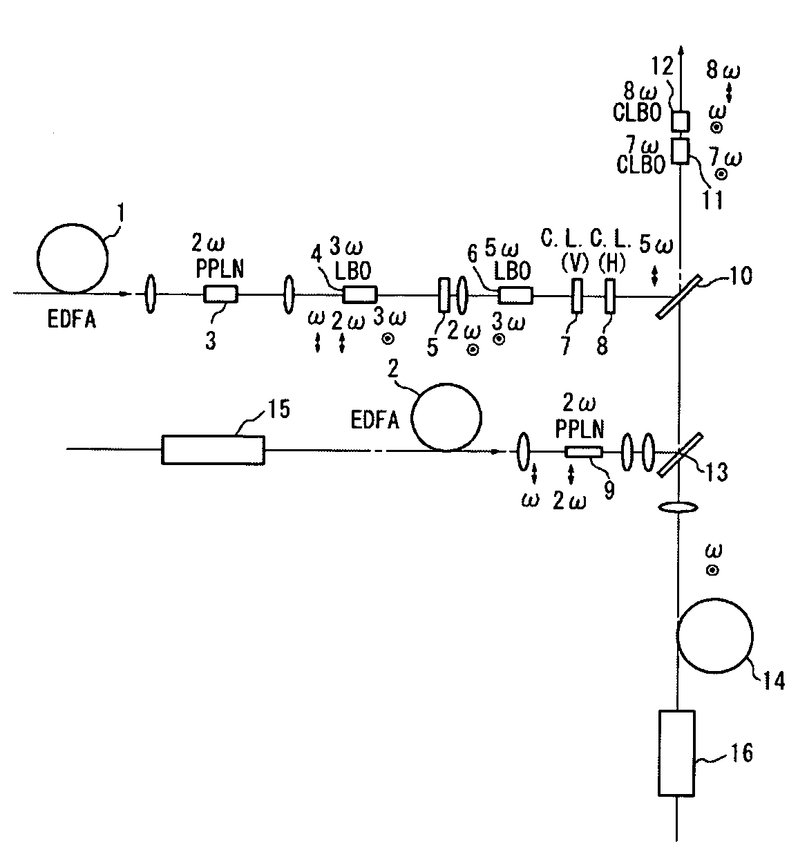
[0031]Working configurations of the present invention will be described below with reference to the figures. FIG. 1 is a diagram showing an outline of the optical system of a laser apparatus constituting a first working configuration of the present invention. In FIGS. 1 and 4, the objects indicated by oval shapes are collimator lenses and focusing lenses; an explanation of these lenses is omitted. Furthermore, P polarization is indicated by an arrow symbol, S polarization is indicated by symbols showing a dot inside a circle, the fundamental wave is indicated by ω, and n-th waves are indicated by nω.

[0032]In this working configuration, the fundamental wave (wavelength: 1547 nm) emitted from a single DFB laser (not shown in the figures) branches into three waves, which are respectively amplified by a first EDFA 1, second EDFA 2, and third EDFA 14. However, it would also be possible to amplify fundamental waves emitted from three DFB lasers by means of respective EDFAs. As is shown in...


PUM


Abstract

A fifth harmonic wave is formed from a fundamental wave of P polarization via a second harmonic wave forming optical element 3, a third harmonic wave forming optical element 4, and a fifth harmonic wave forming optical element 6, and a second harmonic wave of P polarization is formed from a fundamental wave of P polarization via a second harmonic wave forming optical element 9. A fundamental wave of S polarization is combined with the second harmonic wave of P polarization described above by a dichroic mirror 13; furthermore, the fifth harmonic wave of P polarization, the fundamental wave of S polarization described above and the second harmonic wave of P polarization are combined by a dichroic mirror 10, and are incident on a seventh harmonic wave forming optical element 11. A seventh harmonic wave of S polarization is formed from the fifth harmonic wave and second harmonic wave of P polarization, and is combined with the fundamental wave of S polarization by being incident on an eighth harmonic wave forming optical element 12, so that an eighth harmonic wave of P polarization is formed.

Description

TECHNICAL FIELD[0001]The present invention relates to a wavelength converting optical system which generates an eighth harmonic wave from semiconductor laser light mainly having long wavelength (light having a frequency that is n times that of the fundamental wave is referred to as an n-th harmonic wave), a laser light source using this optical system, and an exposure apparatus, device for inspecting an object of inspection, and polymer crystal working apparatus utilizing this laser light source.BACKGROUND ART[0002]In recent years, laser light has been used in various applications; for example, laser light has been used in the cutting and working of metals, and as a light source in photolithographic devices used in semiconductor manufacturing apparatuses. Furthermore, laser light has been used in various types of measuring instruments, and in operations and treatment devices used in surgery, ophthalmology, dentistry, and the like.[0003]However, in the case of ArF excimer laser oscil...

Claims


Application Information

Patent Timeline
Patent Type & Authority Patents(United States)
IPC IPC(8): H01S3/10
CPCG02F1/3534G02F1/37G02F2201/16
Inventor TOKUHISA, AKIRAOSHITA, YOSHINORI
Owner NIKON CORP
Why Eureka
Try Eureka