Method and apparatus for variable accuracy inter-picture timing specification for digital video encoding with reduced requirements of division operations

a technology of inter-picture timing and digital video encoding, applied in the field of multi-media compression systems, can solve the problems of large amounts of digital information needed to accurately represent video, and require very high-capacity digital storage systems and high-bandwidth transmission systems. achieve the effect of quick calculation of estimated motion vectors

Active Publication Date: 2008-03-04
APPLE INC
View PDF17 Cites 85 Cited by
  • Summary
  • Abstract
  • Description
  • Claims
  • Application Information

AI Technical Summary

Benefits of technology

[0011]A method and apparatus for performing motion estimation in a video codec is disclosed. Specifically, the present invention discloses a system that quickly calculates estimated motion vectors in a very efficient manner without requiring an excessive number of division operations.
[0012]In one embodiment, a first multiplicand is determined by multiplying a first display time difference between a first video picture and a second video picture by a power of two scale value. This step scales up a numerator for a ratio. Next, the system determines a scaled ratio by dividing that scaled numerator by a second first display time difference between said second video picture and a third video picture. The scaled ratio is then stored to be used later for calculating motion vector estimations. By storing the scaled ratio, all the estimated motion vectors can be calculated quickly with good precision since the scaled ratio saves significant bits and reducing the scale is performed by simple shifts thus eliminating the need for time consuming division operations.

Problems solved by technology

The massive amounts of digital information needed to accurately represent video require very high-capacity digital storage systems and high-bandwidth transmission systems.

Method used


Image

  • Method and apparatus for variable accuracy inter-picture timing specification for digital video encoding with reduced requirements of division operations
  • Method and apparatus for variable accuracy inter-picture timing specification for digital video encoding with reduced requirements of division operations
  • Method and apparatus for variable accuracy inter-picture timing specification for digital video encoding with reduced requirements of division operations

Examples


Embodiment Construction

[0019]A method and system for specifying Variable Accuracy Inter-Picture Timing in a multimedia compression and encoding system with reduced requirements for division operations is disclosed. In the following description, for purposes of explanation, specific nomenclature is set forth to provide a thorough understanding of the present invention. However, it will be apparent to one skilled in the art that these specific details are not required in order to practice the present invention. For example, the present invention has been described with reference to the MPEG multimedia compression and encoding system. However, the same techniques can easily be applied to other types of compression and encoding systems.

Multimedia Compression and Encoding Overview

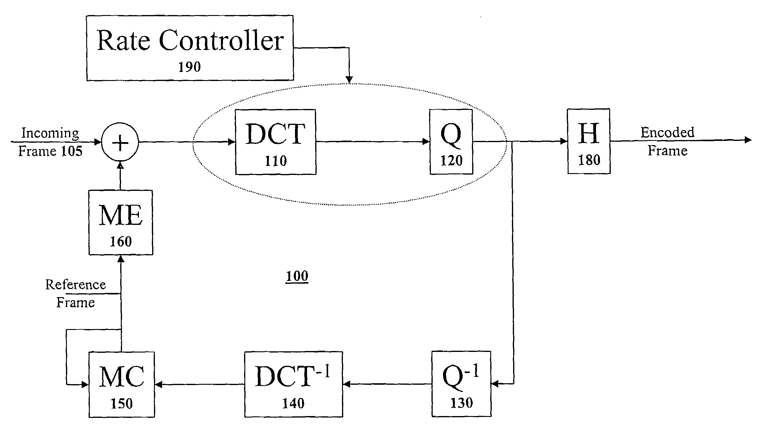
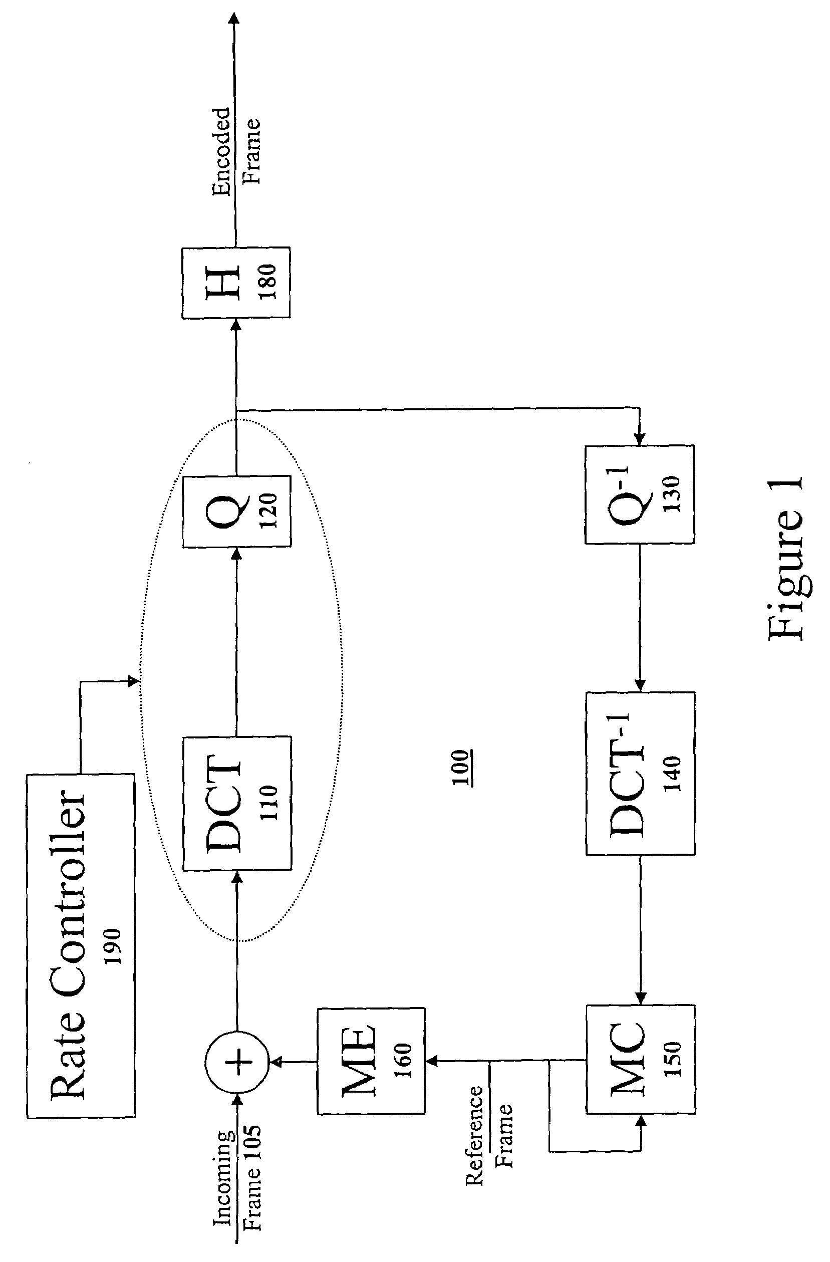
[0020]FIG. 1 illustrates a high-level block diagram of a typical digital video encoder 100 as is well known in the art. The digital video encoder 100 receives an incoming video stream of video frames 105 at the left of the block diagr...


PUM


Abstract

A method and apparatus for performing motion estimation in a digital video system is disclosed. Specifically, the present invention discloses a system that quickly calculates estimated motion vectors in a very efficient manner. In one embodiment, a first multiplicand is determined by multiplying a first display time difference between a first video picture and a second video picture by a power of two scale value. This step scales up a numerator for a ratio. Next, the system determines a scaled ratio by dividing that scaled numerator by a second first display time difference between said second video picture and a third video picture. The scaled ratio is then stored calculating motion vector estimations. By storing the scaled ratio, all the estimated motion vectors can be calculated quickly with good precision since the scaled ratio saves significant bits and reducing the scale is performed by simple shifts.

Description

CLAIM OF BENEFIT TO PRIOR APPLICATIONS[0001]The present application is a continuation application of U.S. patent application Ser. No. 10,313,773, entitled “Method and Apparatus for Variable Accuracy Inter-Picture Timing Specification for Digital Video Encoding With Reduced Requirements for Division Operations”, filed Dec. 6, 2002, now issued as U.S. Pat. No. 6,728,315. U.S. Patent Application Ser. No. 10 / 313,773 claims the benefit under title 35, United States Code, Section 119(e) to the United States Provisional Patent Application having Ser. No. 60 / 398,625, filed Jul. 24, 2002.CROSS REFERENCE TO RELATED APPLICATIONS[0002]This Application is related to U.S. patent application Ser. No. 10 / 313,773, filed Dec. 6, 2002; U.S. patent application Ser. No. 11 / 621,977, filed Jan. 10, 2007; U.S. patent application Ser. No. 11 / 621,979, filed Jan. 10, 2007; U.S. patent application Ser. No. 11 / 621,980, filed Jan. 10, 2007; U.S. patent application Ser. No. 10 / 291,320, filed Nov. 8, 2002; U.S. pa...

Claims


Application Information

Patent Timeline
Patent Type & Authority Patents(United States)
IPC IPC(8): H04N7/12G06K9/36G06T9/00H04N7/26H04N7/36H04N19/94
CPCH04N19/13H04N19/00733H04N19/139H04N19/146H04N19/159H04N19/176H04N19/46H04N19/51H04N19/513H04N19/196H04N19/15H04N19/61H04N19/107H04N19/463H04N19/124H04N19/152H04N19/48H04N19/40H04N19/577H04N19/132H04N7/50H04N19/00781H04N19/00721H04N19/00684H04N19/00587H04N19/00563H04N19/00551H04N19/00545H04N19/00472H04N19/00369H04N19/00278H04N19/00218H04N19/00193H04N19/00187H04N19/0009H04N19/0003H04N19/137H04N19/172H04N19/52H04N19/587H04N19/625
Inventor HASKELL, BARIN GEOFFRYSINGER, DAVID WILLIAMDUMITRAS, ADRIANAPURI, ATUL
Owner APPLE INC
Why Eureka
Try Eureka