
Method for operating an air-breathing engine

a technology of air-breathing engine and engine body, which is applied in the direction of machines/engines, jet propulsion plants, hot gas positive displacement engine plants, etc., can solve the problems of increasing the number of drops which strike the compressor blades, the potential erosive effect thereof, and the negative effect is not provided. , to avoid the effect of potentially negative effects

Active Publication Date: 2008-03-11
ANSALDO ENERGIA SWITZERLAND AG
View PDF14 Cites 20 Cited by
  • Summary
  • Abstract
  • Description
  • Claims
  • Application Information

AI Technical Summary

Benefits of technology

This approach effectively maintains optimal drop size and concentration, reducing erosive effects and control instabilities, ensuring efficient engine performance by continuously adjusting the liquid injection parameters based on real-time measurements.

Problems solved by technology

When drops enter a turbo-compressor, the number of drops which strike the compressor blades, and the potentially erosive effect thereof, increases with the drop size.
This means that if the drop size exceeds a defined limit value, the negative effects rise disproportionately.
The variables measured in this case, however, also do not provide any information as to the atomization characteristics.

Method used


Image

  • Method for operating an air-breathing engine
  • Method for operating an air-breathing engine
  • Method for operating an air-breathing engine

Examples


Embodiment Construction

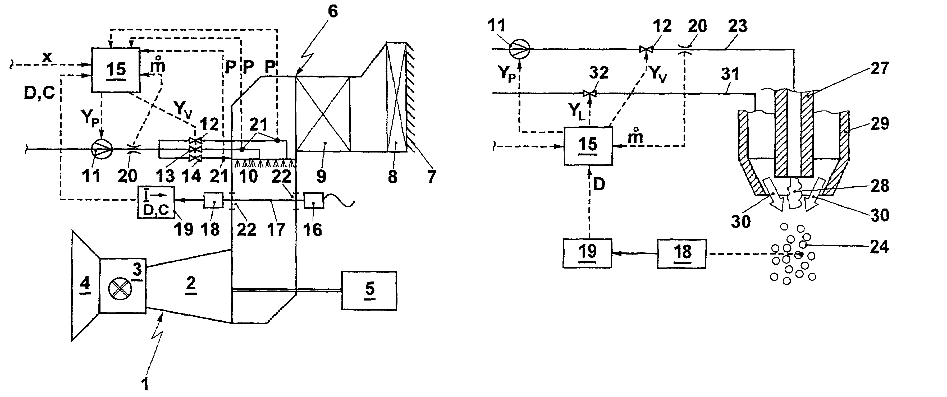
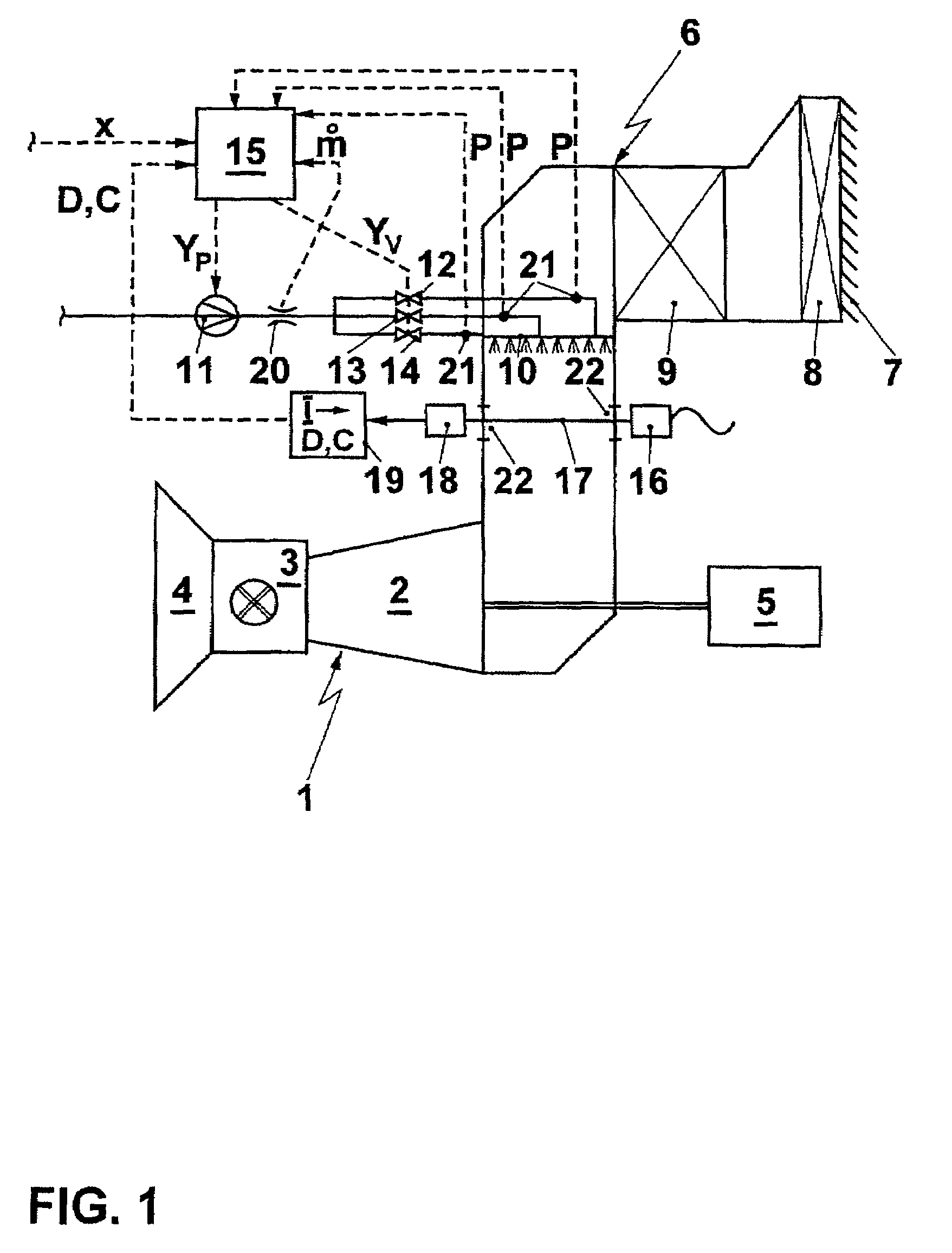
[0022]In accordance with FIG. 1, a gas turboset 1 comprises a compressor 2, a combustion chamber 3 and a turbine 4. A useful power is used to drive a load, for example generator 5, for example via a shaft (indicated without a reference number). The compressor 2 draws air out of the environment, and this air is compressed and passed into the combustion chamber 3, where a compressed hot gas is generated, which is then expanded in a work-performing manner in the turbine 4. Gas turbines and other air-breathing engines are in many applications equipped with special intake paths which allow a defined location for the air inlet to be selected and the intake air to be suitably prepared. The gas turboset illustrated in FIG. 1 has an intake duct 6, through which the intake air flows, upstream of the compressor inlet. This intake duct comprises inlet lamellae 7, the purpose of which is to prevent the ingress of coarse dirt, in particular rainwater. This is followed downstream by an air filter ...


PUM


Abstract

When operating an air-breathing engine, a liquid is injected in atomized form into an air intake duct of the engine. A measurement apparatus for determining the injected drop size or the drop concentration is arranged in or on the intake duct downstream of the location of the injection. These measured values are input into a control system, which controls suitable parameters of the injection apparatus in such a manner that the determined variables are controlled to desired values or into desired value ranges.

Description

CROSS REFERENCE TO RELATED APPLICATIONS[0001]This application claims priority under 35 U.S.C. § 119 to German Application 103 33 208.1 filed on Jul. 22, 2003, and as a continuation application under 35 U.S.C. § 120 to PCT / EP2004 / 051502 filed as an International Application on Jul. 15, 2004 designating the U.S., the entire contents of which are hereby incorporated by reference in their entireties.FIELD OF THE INVENTION[0002]The present invention relates to a method for operating an engine.BACKGROUND OF THE INVENTION[0003]The prior art has disclosed methods for positively influencing the performance data of engines with internal combustion, for example a gas turboset, by evaporative cooling before and / or during the compression of the combustion air. For this purpose, it is customary for water or another liquid to be injected in finely atomized form into the gas stream which has been drawn in. The overriding significance of the atomization quality and the homogeneous distribution of th...

Claims


Application Information

Patent Timeline
Patent Type & Authority Patents(United States)
IPC IPC(8): F02C3/30F02C7/143
CPCF02C7/1435
Inventor JIMENEZ HAERTEL, CARLOSSAVIC, SASHA
Owner ANSALDO ENERGIA SWITZERLAND AG
Learn More