Pipe fitting and assembly using such pipe fittings

a technology of pipe fittings and fittings, applied in the direction of couplings, rod connections, manufacturing tools, etc., can solve the problems of difficult to conduct exact height adjustment, assembly shelves that wobble or show other defects, and problems such as prone to aris

Inactive Publication Date: 2008-03-11
SEKISUI JUSHI KK +1
View PDF13 Cites 19 Cited by
  • Summary
  • Abstract
  • Description
  • Claims
  • Application Information

AI Technical Summary

Benefits of technology

[0011]The aperture of these structures can expose the positioning mark for equipping the central cylinder of the pipe fitting onto the pipe.

Problems solved by technology

However, some problems tend to arise when the fitting is mounted on the pipe P1 according to Japanese Examined Patent Publication No.
By way of example, when the fitting is equipped to the pipe P1 of the former reference or to the pipe of the latter reference in order to assemble a shelf, if the installation operation lacks precision in height dimension, the assembled shelf will wobble or show other defects.
Thus, as far as the installation operation relies on worker's sense, it is difficult to conduct exact height adjustment.

Method used


Image

  • Pipe fitting and assembly using such pipe fittings
  • Pipe fitting and assembly using such pipe fittings
  • Pipe fitting and assembly using such pipe fittings

Examples


first embodiment

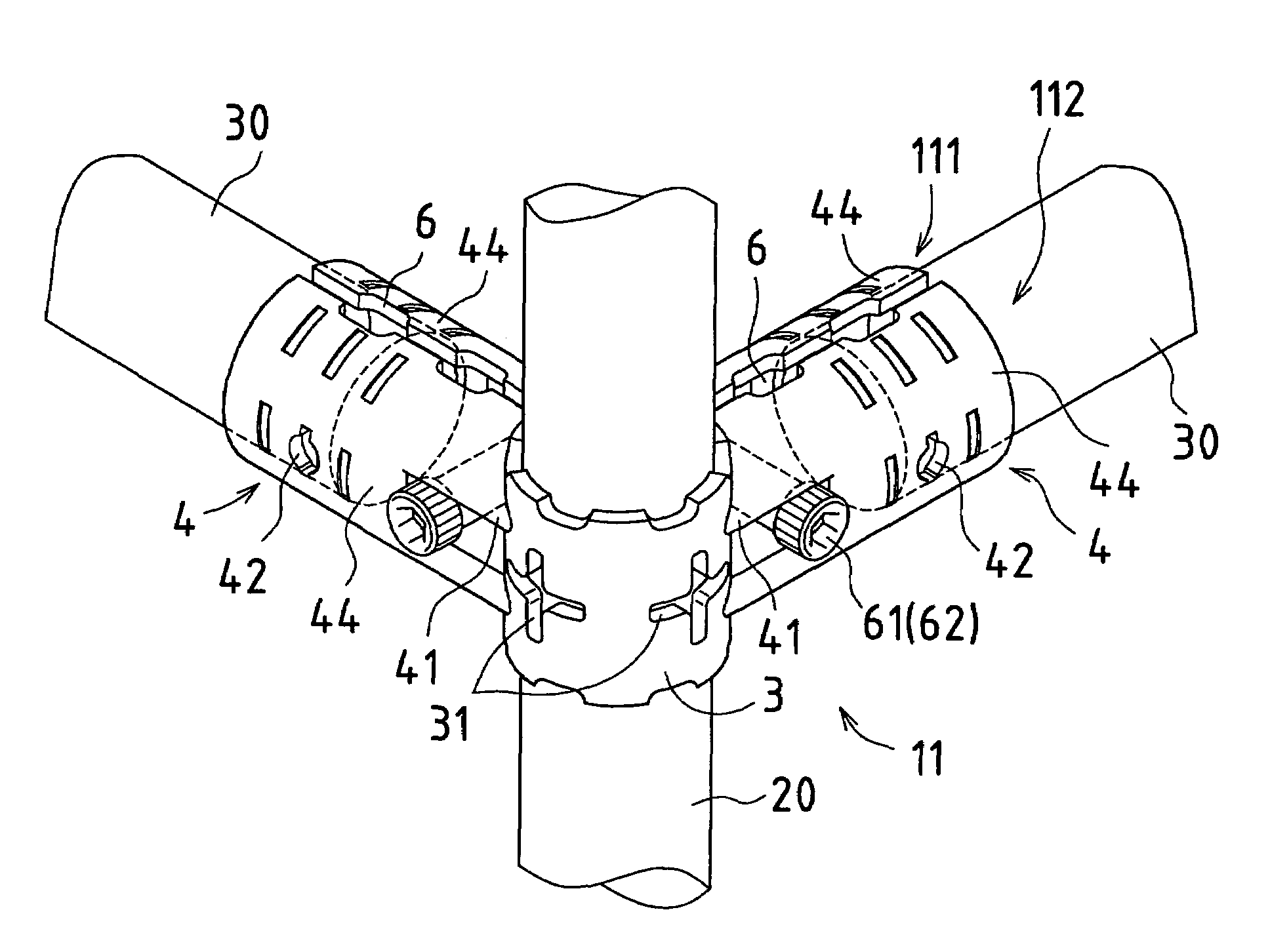
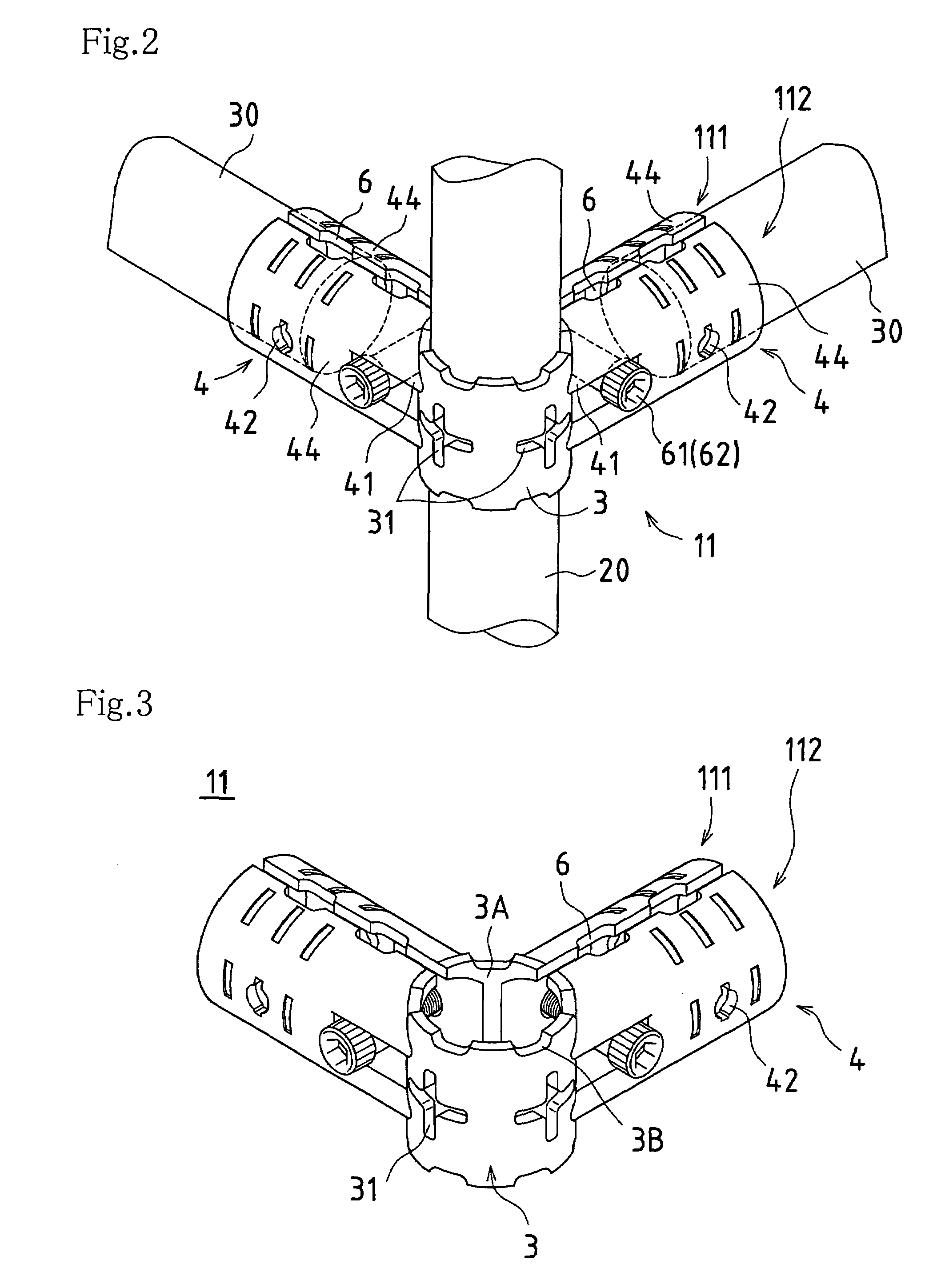
[0046]FIG. 2 is a perspective view which describes the first embodiment of the pipe fitting, with pipes being inserted, according to the present invention. This illustration corresponds to FIG. 1(a). FIG. 3 is a perspective view showing the first embodiment. FIG. 4(a) is a plan view thereof, FIG. 4(b) is a front view thereof, and FIG. 4(c) is a right side view thereof.

[0047]A pipe fitting 11 comprises two split fittings, namely, a ¼-cylindrical split fitting 111 and a ¾-cylindrical split fitting 112. The ¼-cylindrical split fitting 111 is composed of a ¼ cylinder wall 3A of the central cylinder 3 having a 90° arc, and extended half pipes 44, 44 which have a half pipe shape and which project from both ends of the cylinder wall 3A at 90° relative to the cylinder wall 3A. On the other hand, the ¾-cylindrical split fitting 112 is composed of a ¾ cylinder wall 3B of the central cylinder 3 having a 270° arc, and extended half pipes 44, 44 which have a half pipe shape and which project fro...

second embodiment

[0055]FIG. 5 is a perspective view showing the second embodiment of the pipe fitting according to the present invention. FIG. 6(a) is a plan view thereof, FIG. 6(b) is a front view thereof, FIG. 6(c) is a left side view thereof, and FIG. 6(d) is a right side view thereof.

[0056]A pipe fitting 12 comprises two ½-cylindrical single-extension split fittings 121. Each split fitting 121 is composed of a ½ cylinder wall 3C of the central cylinder 3 having a 180° arc, and an extended half pipe 44 which has a half pipe shape and which projects from an end of the cylinder wall 3C at 90° relative to the cylinder wall 3C. Combination of these split fittings 121 creates the central cylinder 3 for receiving a pipe 20 (not shown) and the extended cylinder 4 for receiving a pipe 30 (not shown). In terms of positional relationship, the pipe 20 and the pipe 30 are fixed vertically with respect to each other.

third embodiment

[0057]FIG. 7 is a perspective view showing the third embodiment of the pipe fitting according to the present invention. FIG. 8(a) is a plan view thereof, FIG. 8 (b) is a front view thereof, and FIG. 8(c) is a right side view thereof.

[0058]A pipe fitting 13 comprises two ½-cylindrical double-extension split fittings 131. Each split fitting 131 is composed of a ½ cylinder wall 3C of the central cylinder 3 having a 180° arc, and extended half pipes 44, 44 which have a half pipe shape and which project from both ends of the cylinder wall 3C at 90° relative to the cylinder wall 3C. Combination of these split fittings 131 creates the central cylinder 3 for receiving a pipe 20 (not shown) and the extended cylinders 4 for receiving pipes 30 (not shown). In terms of positional relationship, the pipe 20 and the pipes 30 are fixed vertically with respect to each other.


PUM


Abstract

A pipe fitting of the present invention comprises a combination of a plurality of split fittings and has a central cylinder and an extended cylinder which outwardly projects from the central cylinder, the central cylinder and the extended cylinder being capable of receiving pipes from orthogonal directions with respect to each other. The extended cylinder includes a bolt hole which locates near the central cylinder and which penetrates the extended cylinder. The central cylinder has an aperture provided in a side surface thereof. Each split fitting is fixed on the pipes by a bolt and nut via the respective bolt hole.

Description

TECHNICAL FIELD[0001]The present invention relates to a pipe fitting for connecting pipes of various lengths, and an assembly using such pipe fittings.BACKGROUND ART[0002]In a conventional arrangement for assembling pipes of various lengths with use of fittings, several types of split fittings are combined at the ends of pipes or in the middle of a pipe. Each of these split fittings has pipe support sections whose dimensions and shape conform to the components (i.e. pipes), and forms tubular sections when combined with each other. Into these tubular sections, pipes are inserted and fixed by bolts and nuts in a clamped manner. As is already known, this structure is utilized to assemble a plurality of pipes in an orthogonal arrangement, freely in the lengthwise and widthwise directions.[0003]As an example of the prior art, Japanese Examined Patent Publication No. S53-25170 discloses a pipe connection method and a fitting therefor. This method utilizes a split fitting which has an arc-...

Claims


Application Information

Patent Timeline
Patent Type & Authority Patents(United States)
IPC IPC(8): F16B7/04E04H12/00
CPCF16B7/0426F16B7/0486Y10T403/20Y10T403/648Y10T403/341Y10T403/34F16B2200/509F16B7/04
Inventor NAKAHORI, HIROYUKIHIROOKA, TOMOAKI
Owner SEKISUI JUSHI KK
Why Eureka
Try Eureka