Electrical connector

Inactive Publication Date: 2008-03-11
HON HAI PRECISION IND CO LTD
View PDF6 Cites 11 Cited by
  • Summary
  • Abstract
  • Description
  • Claims
  • Application Information

AI Technical Summary

Benefits of technology

[0008]An object of the present invention is to provide an electrical connector connecting a chip module to a printed circuit

Problems solved by technology

However, connection apparatus abovementioned comprises many compon

Method used


Image

  • Electrical connector
  • Electrical connector
  • Electrical connector

Examples


Embodiment Construction

[0016]Reference will now be made to the drawings to describe the present invention in detail.

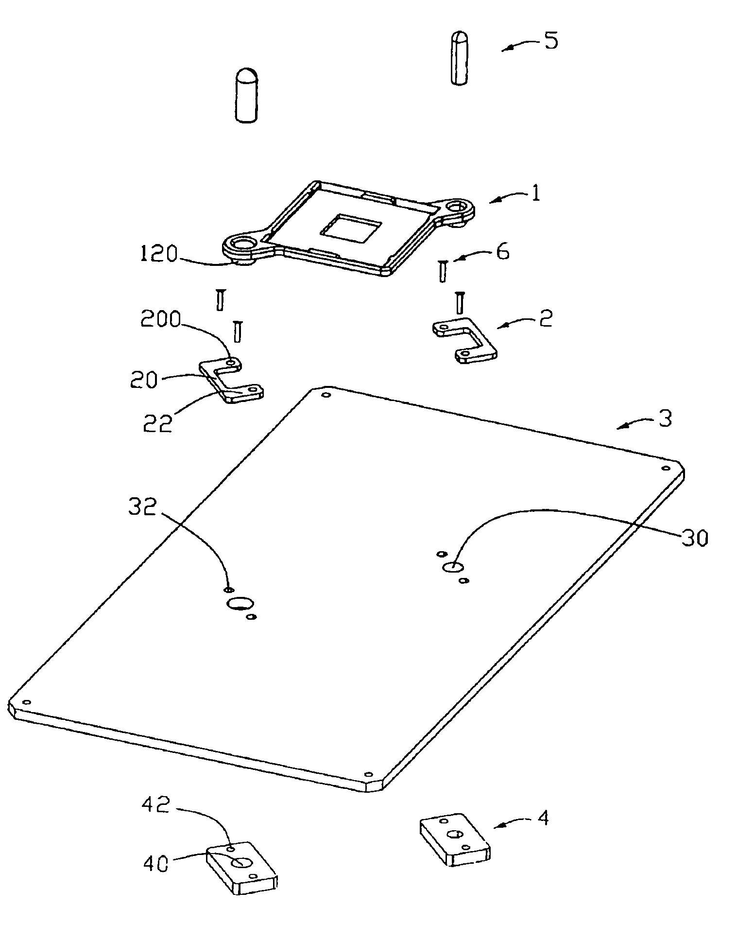
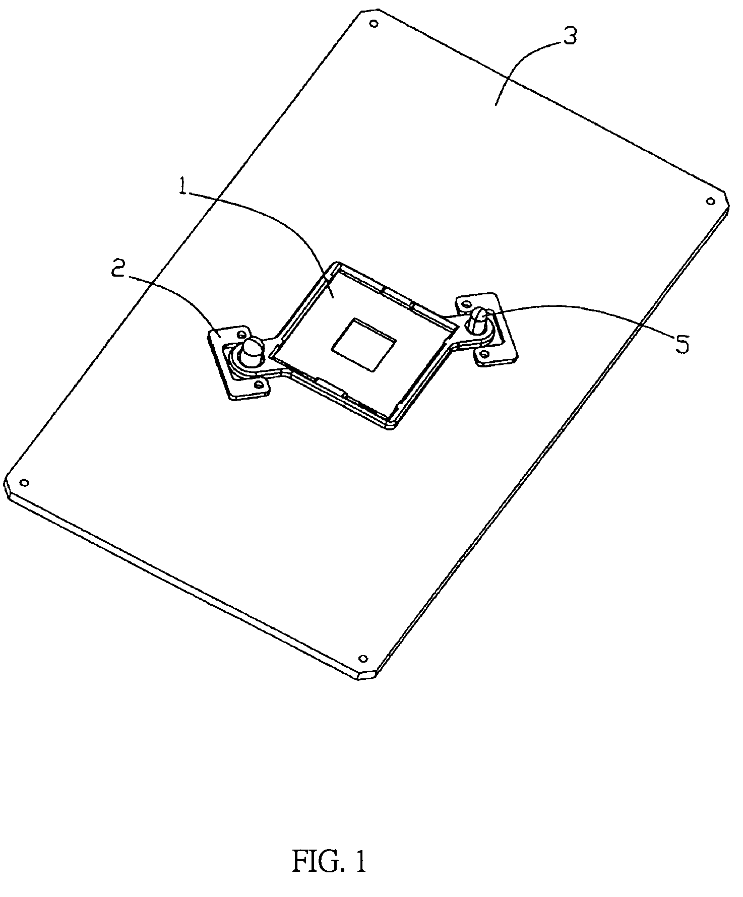
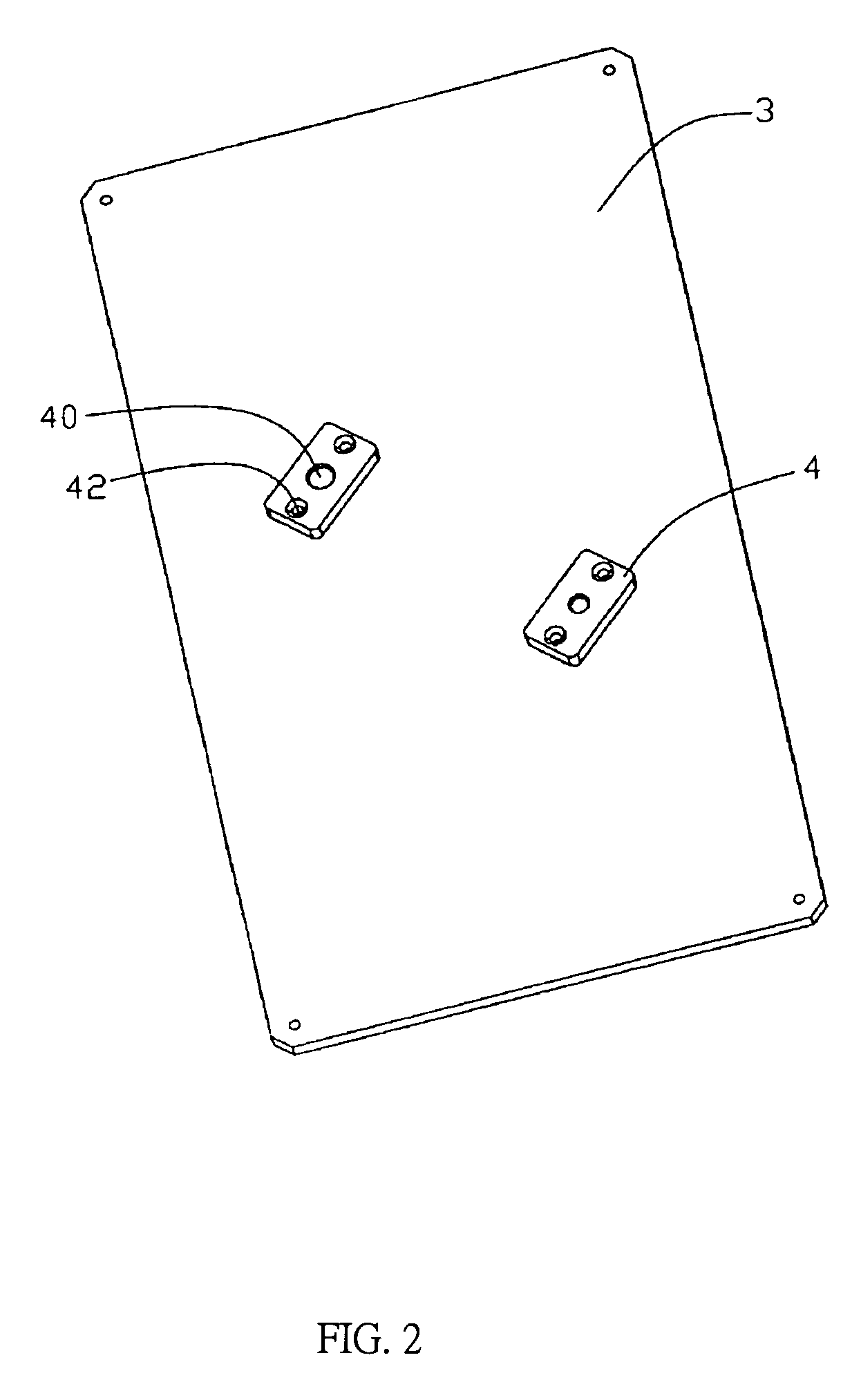
[0017]Referring to FIGS. 1-4, an electrical connector in accordance with the preferred embodiment of the present invention is adapted for electrically connecting an electronic package such as a chip module (not shown) with a printed circuit board such as a printed circuit board (PCB) 3. The electrical connector comprises a housing 1 fixed on the PCB 3, a pair of upper alignment plates 2 and a pair of lower alignment plates 4 attached on an upper surface and a lower surface of the printed circuit board 3 respectively for enforcing the connection between the housing 1, terminals and the printed circuit board 3, a pair of alignment members 5 for attaching the housing 1 and lower alignment plates 4 to the printed circuit board 3 respectively and a number of alignment pins 6 for further enforcing the engagement between the upper alignment plates 2, the lower alignment plates 4 and the printed cir...


PUM


Abstract

An electrical connector for electrically connecting a chip module with a printed circuit board (3), the printed circuit board (3) defines a number of second holes (3) and a central hole, (3) the electrical connector comprises, a housing (3) fixed on the printed circuit board (3) comprising a plurality of passageways (3) and a number of holes (3) therein, a plurality of terminals received in the passageways of the housing (3), at least one upper alignment plate (3) attached on a top surface of the printed circuit board (3) with a receiving portion (3) for receiving corner of the housing (3) and a number of first holes (3) therein, at least lower alignment (3) attached on a bottom surface (3) of the printed circuit board (3) corresponding to the upper alignment plate (3) with a number of third hole (3), a number of alignment member (3) inserted into the first holes (3), and the second holes (3), the third holes (3) for connecting the upper alignment plate (3), the lower alignment plate (3) to the printed circuit board (3), wherein the ear portions (3) engage with the receiving portion (3) of the upper alignment plate (3) by interfering engagement.

Description

BACKGROUND OF THE INVENTION[0001]1. Field of the Invention[0002]The present invention relates to an electrical connector for electrically connecting an electronic package with a printed circuit board.[0003]2. Description of Prior Art[0004]Electrical connectors are widely used in personal computer (PC) systems to electrically connect chip modules with printed circuit boards (PCBs). An electrical connector comprises an insulative housing, a multiplicity of terminals received in the housing in a rectangular array, a metal cover pivotally mounted to the housing, and a lever attached to the housing and a stiffener mounted on a lower end of the housing.[0005]A related art please refer to the U.S. Pat. No. 6,969,267 which discloses an apparatus comprising: a retention frame having frame portions to carry fasteners; a socket carrying a first set of contacts to engage contacts of an IC and positioned within the retention frame such that portions of the frame surround the socket and such that...

Claims


Application Information

Patent Timeline
IPC IPC(8): H01R12/00H01R12/71
CPCH01R12/7047H01R12/7076
Inventor MCHUGH, ROBERT G.FAN, CHIA-WEI
Owner HON HAI PRECISION IND CO LTD
Why Eureka
Try Eureka