Phased array radio frequency pulse generator

a radio frequency pulse and generator technology, applied in the direction of pulse manipulation, impedence networks, electrical apparatus, etc., can solve the problems of limited power handling capacity of conventional ferrite phase shifters, limited power handling capacity of diodes phase shifters, and inoperable phased arrays

Active Publication Date: 2008-03-11
BAE SYSTEMS PLC
View PDF5 Cites 11 Cited by
  • Summary
  • Abstract
  • Description
  • Claims
  • Application Information

AI Technical Summary

Benefits of technology

[0010]According to one aspect of the present invention there is provided a phased array radio frequency pulse generator for producing a plurality of pulsed radio frequency electrical signals, including a plurality of radio frequency pulse generator units each having a non-linear dispersive electrical circuit incorporating at least one non-linear element including a material sensitive to low power signals and a means for producing a variable power control signal and applying the control signal to the at least one non-linear element to modify the extent of the non-linearity of the element and thereby vary the timing of the radio frequency electrical output signal generated, and means for adjusting the value of the control signals provided in each unit to vary the relative phases of the output signals from the radio signal pulsed generator units in a phased array on a pulse to pulse basis.

Problems solved by technology

The operation of phased array transmitters is common place at low power levels from each array element such as less than 100 kW but existing radio frequency sources which are used to produce higher power of up to 100 MW or more radio frequency pulses are not operable in phased arrays.
The power handling capacity of such diode phase shifters is generally limited to about 1 kW peak power and the power handling capacity of conventional ferrite phase shifters is limited to about 100 kW peak power.
These delays may be introduced by including switched delay lines or switched circulators but however introduced these conventional electronically controlled delay devices are also limited in power handling capacity to approximately 100 kW peak power.

Method used


Image

  • Phased array radio frequency pulse generator
  • Phased array radio frequency pulse generator
  • Phased array radio frequency pulse generator

Examples


Embodiment Construction

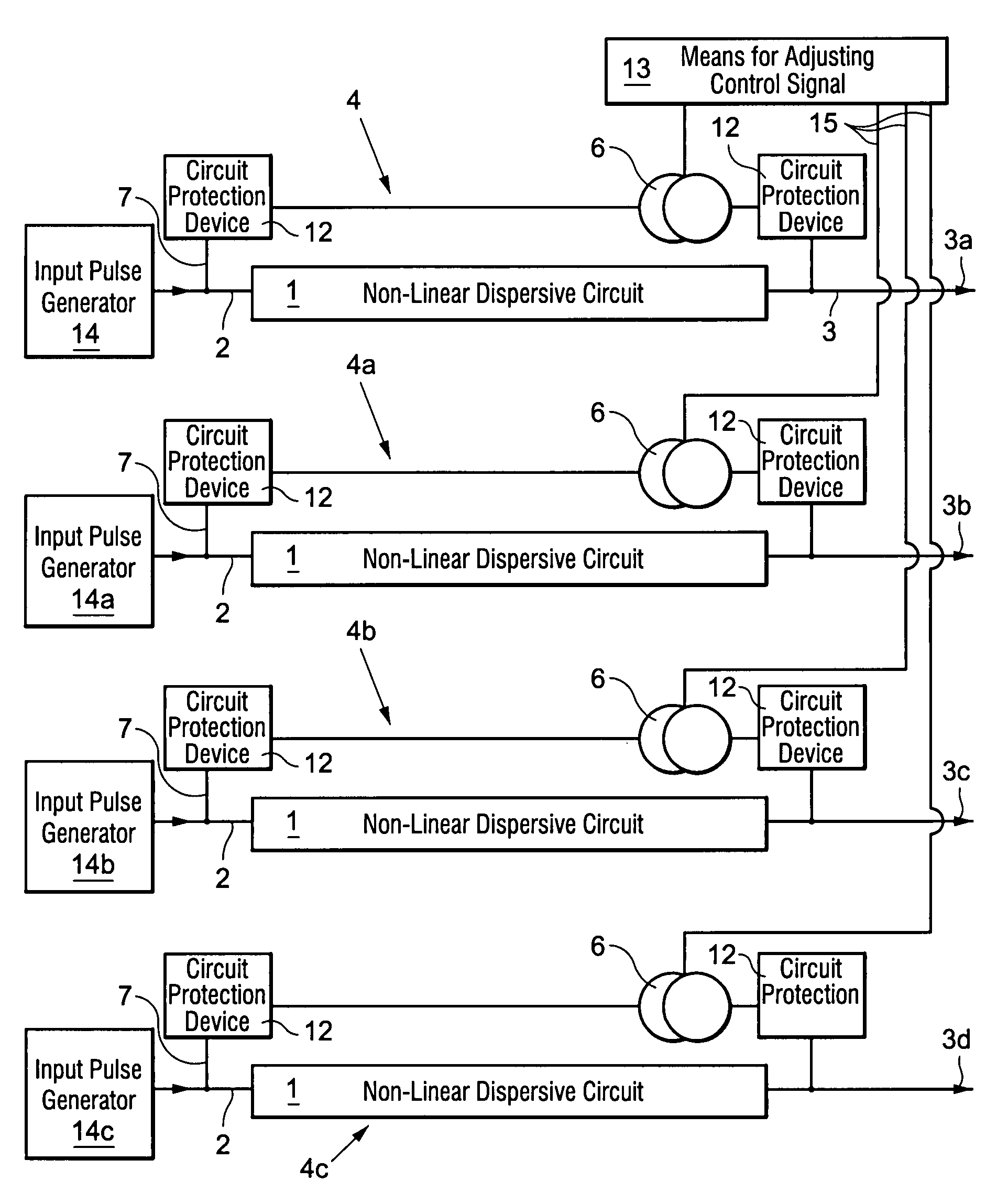
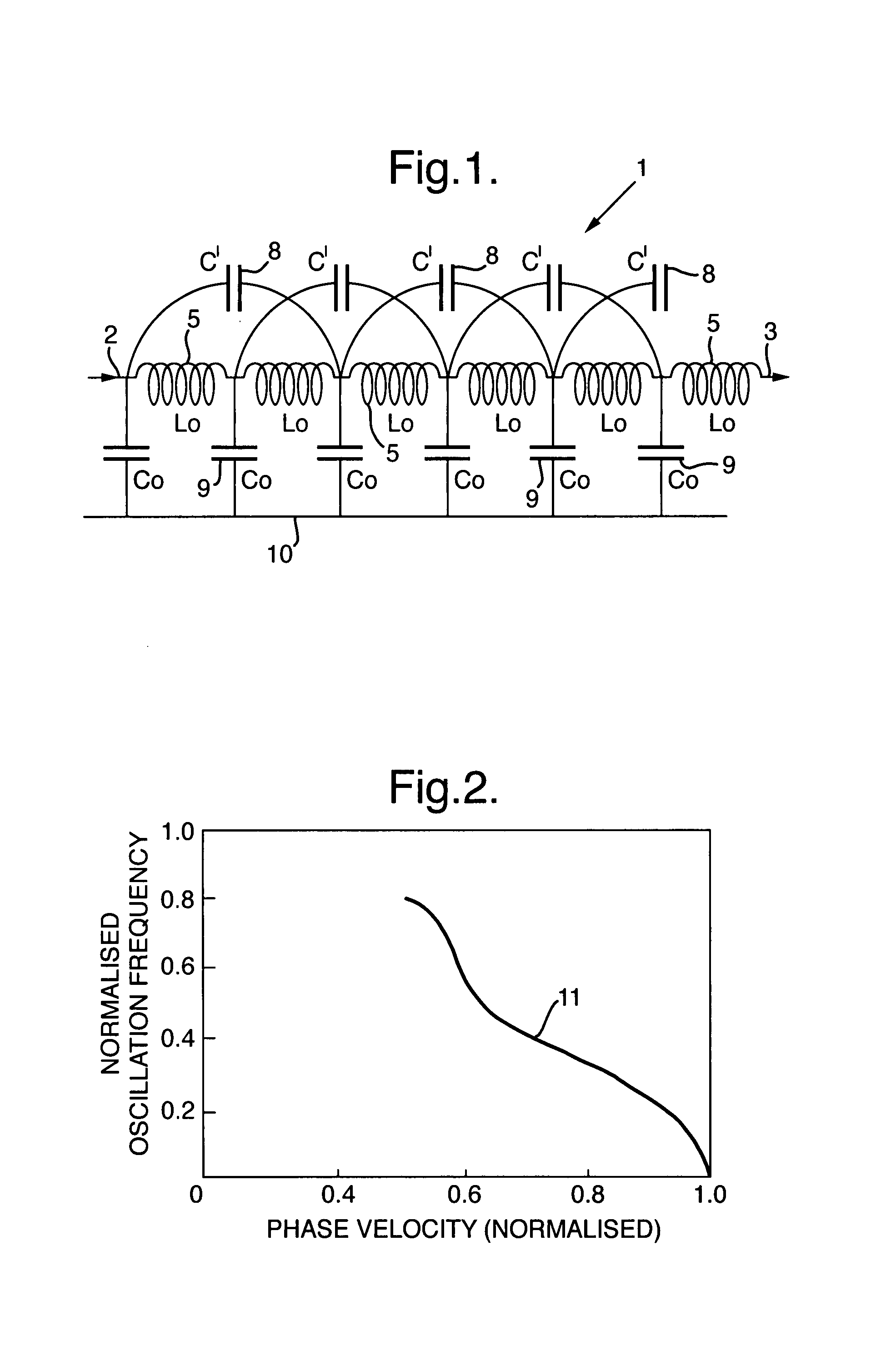
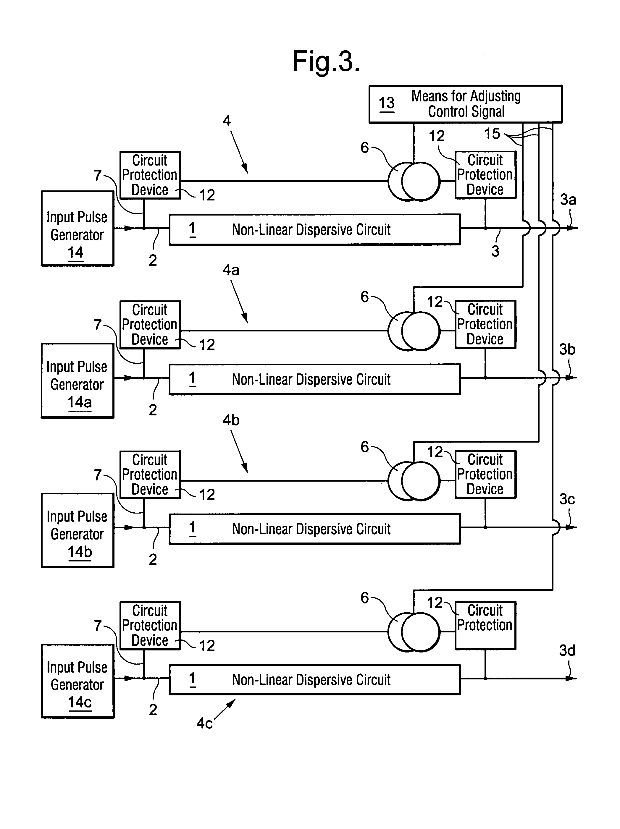
[0020]A pulsed radio frequency signal is produced according to the present invention by modulation of an electrical pulse in a non-linear dispersive electrical circuit generally indicated at 1 in FIG. 1 of the accompanying drawings. An electrical pulse that has a short pulse rise time and a flat top although the flat top is not essential, is injected into the circuit 1 at 2. The non-linear and dispersive characteristics of the circuit 1 modify the shape of the pulse that is injected at 2 to produce a radio frequency output pulse at point 3. The circuit 1 does not require the production of electron beams and subsequent interaction with a resonant mechanical structure and the circuit may be implemented in solid state as it does not contain vacuum elements, large magnets or gas supplies. The radio frequency formation process in the circuit 1 is a complex process that depends on the interaction of non-linearity and dispersion. Factors such as the efficiency of radio frequency generation...


PUM


Abstract

A phased array radio frequency pulse generator includes a plurality of radio frequency pulse generator units (4, 4a, 4b, 4c) each having a non-linear dispersive electrical circuit (1) incorporating at least one non-linear element (5) including a material sensitive to low power signals (7) and a means (6) for producing a variable power control signal (7) and applying it to be at least one non-linear element (5) to modify the extent of the non-linearity of the element and thereby vary the timing of the radio frequency electrical output signal generated, and means (13) for adjusting the value of the control signals (7) provided in each unit (4, 4a, 4b, 4c), to vary the relative phases of the output signals from the units (4, 4a, 4b, 4c) in a phased array on a pulse to pulse basis.

Description

BACKGROUND OF THE INVENTION[0001]1. Field of the Invention[0002]This invention relates to a phased array radio frequency pulse generator particularly suitable for producing a plurality of pulsed radio frequency electrical signals.[0003]2. Discussion of Prior Art[0004]In the field of high power radio frequency and microwave generators it is advantageous to be able to operate a plurality of individual sources in a phased array. By the term high power is meant peak powers of at least one MW and preferably as high as peak powers of at least 100 MW. Additionally in this specification the term radio frequency is used to cover radiation in the high frequency, very high frequency, ultra high frequency and microwave regions of the electromagnetic spectrum.[0005]Operating a plurality of individual radio frequency transmitter sources in an array in which the relative phase of radio frequency emission from each element can be controlled is desirable. This allows the generation of high radiation...

Claims


Application Information

Patent Timeline
IPC IPC(8): H01Q3/26H01Q3/30H03H7/32
CPCH01Q3/26H01Q3/30H03K5/12H04B1/7174
Inventor SEDDON, NIGELSPIKINGS, CHRISTOPHER R.
Owner BAE SYSTEMS PLC
Why Eureka
Try Eureka