
Magnetic recording and reproduction apparatus

a technology of applied in the field of magnetic recording and reproduction apparatus, can solve the problems of increasing the cost of the loading mechanism, affecting the size and cost of the video tape recorder, and increasing the number of components, so as to achieve the effect of simple, compact, and reduced cos

Inactive Publication Date: 2008-03-11
PANASONIC CORP
View PDF6 Cites 0 Cited by
  • Summary
  • Abstract
  • Description
  • Claims
  • Application Information

AI Technical Summary

Benefits of technology

[0021]Thus, the invention described herein makes possible the advantages of providing a magnetic recording and reproduction apparatus including a simple, compact and low-cost loading mechanism which has a smaller number of components and can be designed with a higher level of freedom.

Problems solved by technology

Especially, a loading mechanism, which has a very complicated structure and includes a large number of components, significantly influences the size and cost of the video tape recorders.
The above structure requires the rail, which is a complicated and a large component, and also requires an attaching section for securing the rail to the chassis, a space for the attaching section, and screws for attaching the rail to the chassis.
As a result, the number of components is increased, which in turn increases the cost of the tape loading mechanism.
In addition, the size of the mechanism is enlarged for obtaining the space for the rail, and the freedom of design of the tape loading section is restricted.

Method used


Image

  • Magnetic recording and reproduction apparatus
  • Magnetic recording and reproduction apparatus
  • Magnetic recording and reproduction apparatus

Examples


Embodiment Construction

[0034]Hereinafter, the present invention will be described by way of illustrative examples with reference to FIGS. 1 through 9.

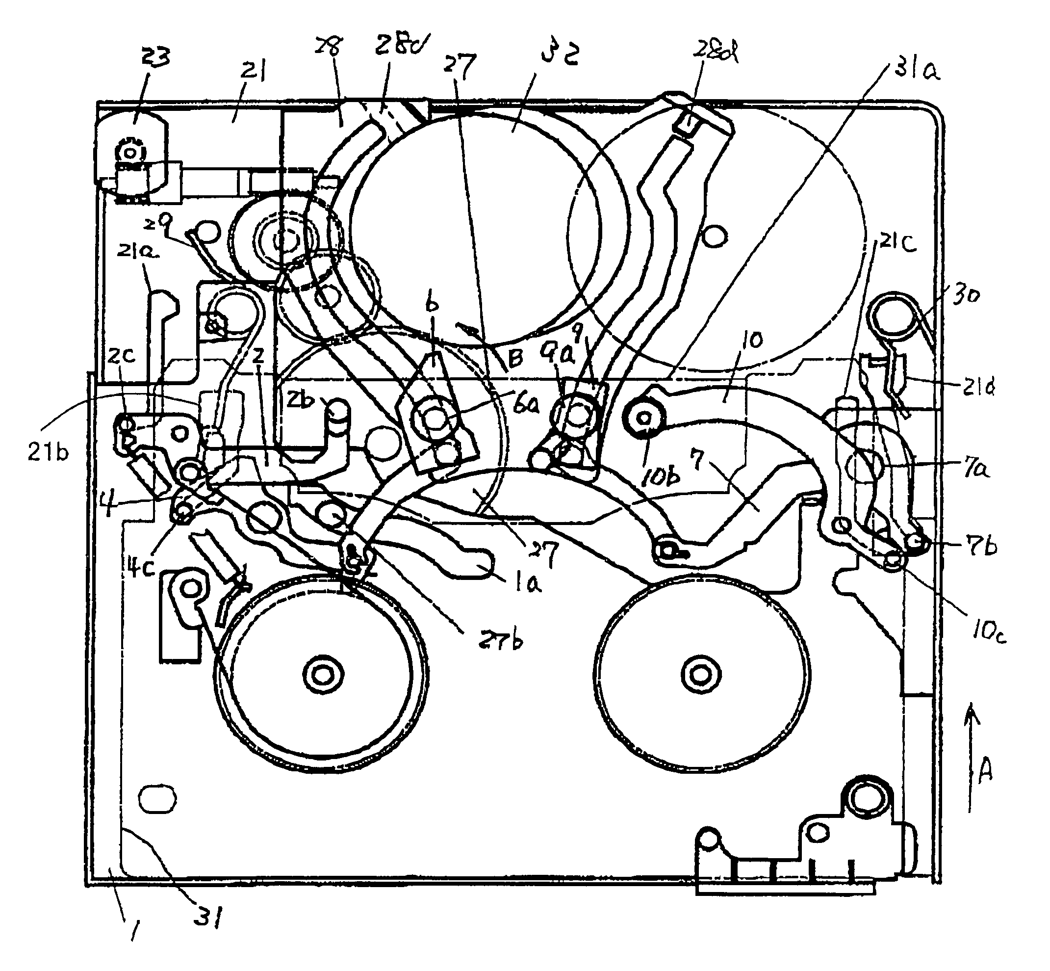
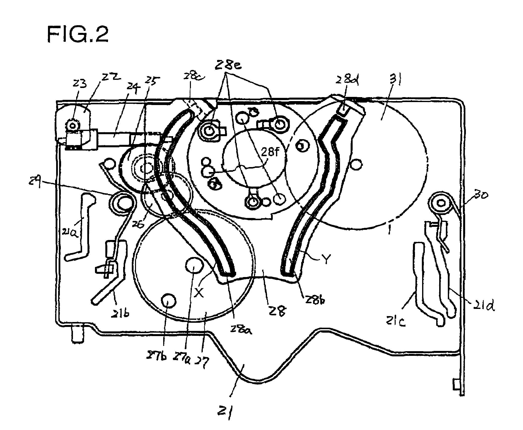
[0035]A magnetic recording and reproduction apparatus according to the present invention includes a chassis structure. The chassis structures includes a main chassis 21 and a sub chassis 1.

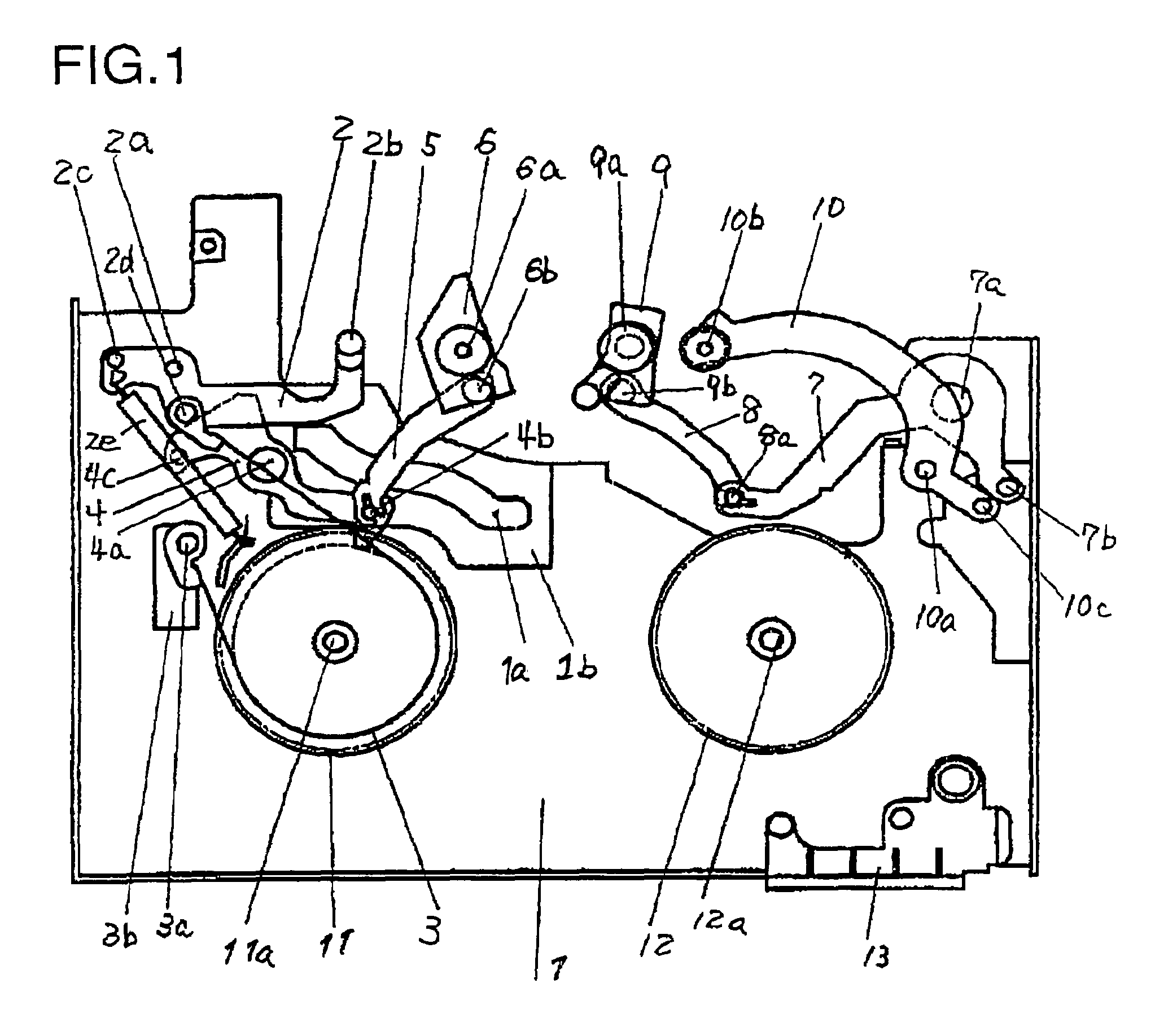
[0036]First, a structure of the sub chassis 1 of the magnetic recording and reproduction apparatus will be described. FIG. 1 is a plan view of the sub chassis 1.

[0037]A sub chassis 1 has a TR arm 2, an S boat 6, a T boat 9 and a T3 arm 10 provided thereon. These tape pull-out members 2, 6, 9 and 10 act to pull out a magnetic tape (not shown in FIG. 1) from a tape cassette.

[0038]The TR arm 2 is supported so as to be pivotable about a support 2a on the sub chassis 1. A TR post 2b is provided on a top surface of one end of the TR arm 2, and a TR arm driving pin 2c is provided on a bottom surface of the other end of the TR arm 2.

[0039]The T3 arm 10 is supported so as to be piv...


PUM

PropertyMeasurementUnit
magneticaaaaaaaaaa
sizeaaaaaaaaaa
forceaaaaaaaaaa

Abstract

A magnetic recording and reproduction apparatus includes a rotatable head cylinder for recording information to, and / or reproducing information from, a magnetic tape; a tape pull-out member for pulling out the magnetic tape; and a guide member for guiding the tape pull-out member. The tape pull-out member is engaged with a groove formed in the guide member. The tape pull-out member is movable between a first position and a second position along the groove. The first position is a position at which information recording to, and information reproduction from, the magnetic tape is possible. The second position is a position at which information recording to, and information reproduction from, the magnetic tape is impossible. The rotatable head cylinder is provided on a cylinder holding member integrally formed with the guide member. A profile of the groove is continuous with no gap.

Description

[0001]This non-provisional application claims priority under 35 U.S.C., §119(a), on Patent Application No. 2003-105082 filed in Japan on Apr. 9, 2003, the entire contents of which are hereby incorporated by reference.BACKGROUND OF THE INVENTION[0002]1. Field of the Invention[0003]The present invention relates to a magnetic recording and reproduction apparatus for recording information to, and / or reproducing information from, a magnetic tape.[0004]2. Description of the Related Art[0005]Recently, in the field of magnetic recording and reproduction apparatuses, reduction of size, reduction of number of components, and simplification of structure have been actively pursued. Especially, a loading mechanism, which has a very complicated structure and includes a large number of components, significantly influences the size and cost of the video tape recorders. The development of the loading mechanism is very important.[0006]Hereinafter, a conventional tape loading mechanism described in Ja...

Claims


Application Information

Patent Timeline
Patent Type & Authority Patents(United States)
IPC IPC(8): G11B15/665
CPCG11B15/6656
Inventor KONISHI, AKIOHIRABAYASHI, KOICHIROSAITO, YOSHIYUKIKURUMATANI, HIROSHI
Owner PANASONIC CORP
Learn More