Method and apparatus for automatic and dynamic vessel detection

a detection method and dynamic technology, applied in the field of digital image processing technique, can solve the problems of large number of false positives (fps) that occur in the vascular region, large number of fps, and increase the sensitivity of the calcification detection algorithm

Inactive Publication Date: 2008-03-11
FUJIFILM CORP
View PDF13 Cites 66 Cited by
  • Summary
  • Abstract
  • Description
  • Claims
  • Application Information

AI Technical Summary

Problems solved by technology

A key problem with the aforementioned methodology is the large number of false positives (FPs) that occur in vascular regions as the sensitivity of the calcification detection algorithm is increased.
Such large number of FPs occurs because the calcification detection algorithm is easily confused by high frequency structure of vessels present in mammography images.
An additional challenge to accurate detection and recognition of calcifications is the fact that signals generated by isolated calcifications are similar to signals generated by vessels.
The techniques currently used to detect and / or enhance the appearance of vascular images in retinal images or arteriograms (DSA) do not work for mammography.
The general problem with these approaches is that the edge profiles are not always manifested with a strong contrast against the background.
Furthermore, in basing edge detection solely on edge derivatives, one is highly susceptible to noise in images leading to non-robust results.
However, with the method described in this work, one will have to manually select a starting point to begin tracking.
Secondly, the use of a matched filter in the above mentioned application to enhance the profile of vessels works only under the assumption of a known structure and scale of vessels, and a low level of image noise.
Since vessels present in mammography images have discontinuous edges and exhibit high noise, one needs to use additional constraints in edge detection.

Method used


Image

  • Method and apparatus for automatic and dynamic vessel detection
  • Method and apparatus for automatic and dynamic vessel detection
  • Method and apparatus for automatic and dynamic vessel detection

Examples


Embodiment Construction

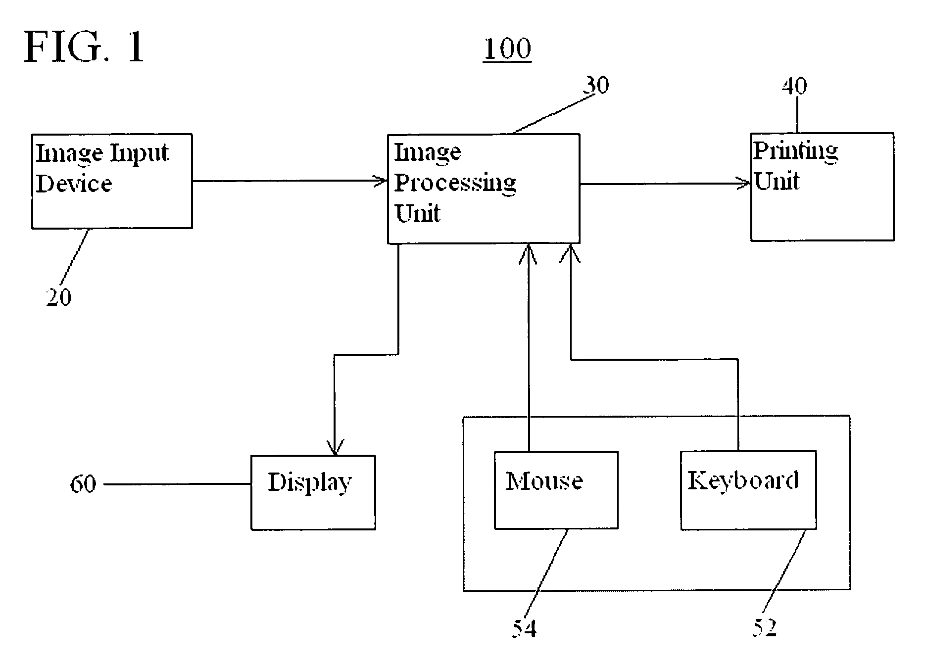
[0032]Aspects of the invention are more specifically set forth in the accompanying description with reference to the appended figures. FIG. 1 is a block diagram of a system for automatically detecting vessels in a diagnostic image according to an embodiment of the present invention. The system 100 illustrated in FIG. 1 includes the following components: an image input device 20; an image processing unit 30; a printing unit 40; a user input unit 50; and a display 60. Operation of the system in FIG. 1 will become apparent from the following discussion.

[0033]The image input device 20 provides digital image data representing a diagnostic image. The image input device 20 may be one or more of any number of devices providing digital image data derived from a radiological film or a digital system. Such an input device may be a scanner for scanning black and white or color images from a film-screen. The input device may be one or more of any number of devices for providing digital data deri...


PUM


Abstract

A method and an apparatus automatically detect vessels in a diagnostic image. The method according to one embodiment accesses digital image data representing a diagnostic image; detects vessel candidates in the diagnostic image by processing the diagnostic image data, the step of detecting vessel candidates including identifying edge pixel pairs of vessels in a diagnostic image by iteratively adjusting a plurality of constraints relating to a general direction and shape of a vessel for a next iteration of edge pixel pair identification in a diagnostic image; and determines whether the plurality of edge pixel pairs form a vessel using learned features.

Description

BACKGROUND OF THE INVENTION[0001]1. Field of the Invention[0002]The present invention relates to a digital image processing technique, and more particularly to a method and apparatus for detecting vessels in a diagnostic image.[0003]2. Description of the Related Art[0004]Medical problems can be diagnosed from mammography images by recognizing and detecting microcalcifications. A key problem with the aforementioned methodology is the large number of false positives (FPs) that occur in vascular regions as the sensitivity of the calcification detection algorithm is increased. An example of an FP is a vascular region mistakenly identified as a microcalcification. Such large number of FPs occurs because the calcification detection algorithm is easily confused by high frequency structure of vessels present in mammography images. An additional challenge to accurate detection and recognition of calcifications is the fact that signals generated by isolated calcifications are similar to signa...

Claims


Application Information

Patent Timeline
Patent Type & Authority Patents(United States)
IPC IPC(8): G06K9/00
CPCG06T7/0012G06T7/0083G06T2207/10116G06T2207/30068G06T2207/30101G06T7/12
Inventor OAKLEY, JONATHAN DAVIDRUSSAKOFF, DANIELHASEGAWA, AKIRA
Owner FUJIFILM CORP
Why Eureka
Try Eureka