
Implantable medical lead and system, and method of use thereof

a medical lead and implantable technology, applied in the field of medical leads, can solve the problems of increasing length, adding complexity and cost, and being difficult to push, and achieving the effect of significantly longer leads having a stiffening member within and being somewhat unwieldy

Inactive Publication Date: 2008-03-11
MEDTRONIC INC
View PDF4 Cites 48 Cited by
  • Summary
  • Abstract
  • Description
  • Claims
  • Application Information

AI Technical Summary

Benefits of technology

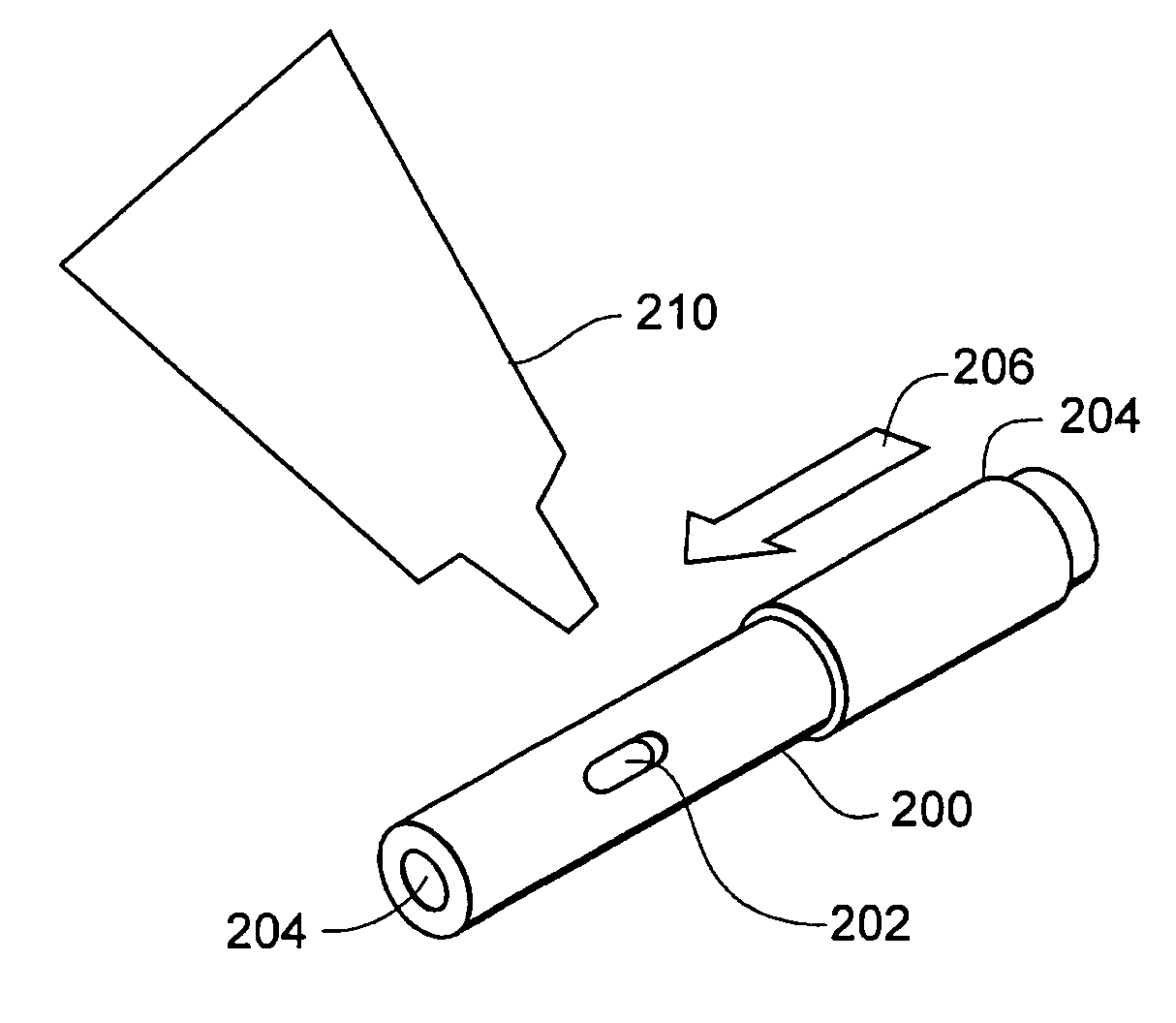
[0013]Some exemplary lead embodiments have no preformed stylet port to allow access from the lead body exterior to the stylet lumen within. Such leads may require formation of a stylet access port through the lead body sidewall. To avoid inserting the stylet through the conductor, some leads have an indicia of radial position on the lead body. The indicia can indicate a radial position about the lead body at which the insertion of a stylet into the lead body will not sever the conductors. Such indicia can be visible stripes or dots in some embodiments. The indicia can also be a depression or a longitudinal groove formed into the lead body. The indicia can be used to properly position a stylet to be inserted into the lead body, as well as to position an introducer or a hole-forming device properly on the lead body.
[0018]In use, an exemplary implantable lead having the desired total length and suitable characteristics is selected for implantation. The lead preferably has a stylet lumen extending between the lead side wall stylet port and the lead distal region. The length between the stylet port and the end of the stylet lumen is preferably dimensioned to receive the stylet, regardless of the total lead length. An introducer needle can be advanced into the body near the implantation site. The stiffening member or stylet can be inserted into the lead stylet port and further distally into the lead to stiffen the lead distal region. The stiffened lead can be inserted through the lumen of the introducer needle and further distally from the needle to the target site. The stylet can be retracted from the lead, and the introducer needle retracted as well, leaving the lead proximal region extending from the body. In some methods, the lead proximal end is coupled to a lead extension before being tunneled into the body to fully implant the lead.
[0020]Exemplary embodiments of the lead, lead assembly, and lead implantation methods allow for implanting a variety of lead lengths while stiffening only the lead distal portion. The lead portion disposed proximal of the stylet port need not be stiffened and / or include a stylet lumen within. This remaining lead proximal portion can be sufficiently long to eliminate the need for a lead extension by not requiring that the entire lead length accept a stylet to provide for stiffening. A single length stylet may thus be used with a family of leads, each having a different total length, but having a similar length stylet lumen within.

Problems solved by technology

The lead, commonly formed of a polymeric material and being very small in cross section, is typically very floppy and not pushable.
The extension, while adding length, also adds complexity and cost.
While this is possible, a significantly longer lead having a stiffening member within would be somewhat unwieldy.
For example, a 50 cm long stylet inserted within a 50 cm long lead would be difficult for the treating physician to maneuver.
This aspect is significantly limiting, given that the treatment site is the spinal cord, where care must be exercised.

Method used


Image

  • Implantable medical lead and system, and method of use thereof
  • Implantable medical lead and system, and method of use thereof
  • Implantable medical lead and system, and method of use thereof

Examples


Embodiment Construction

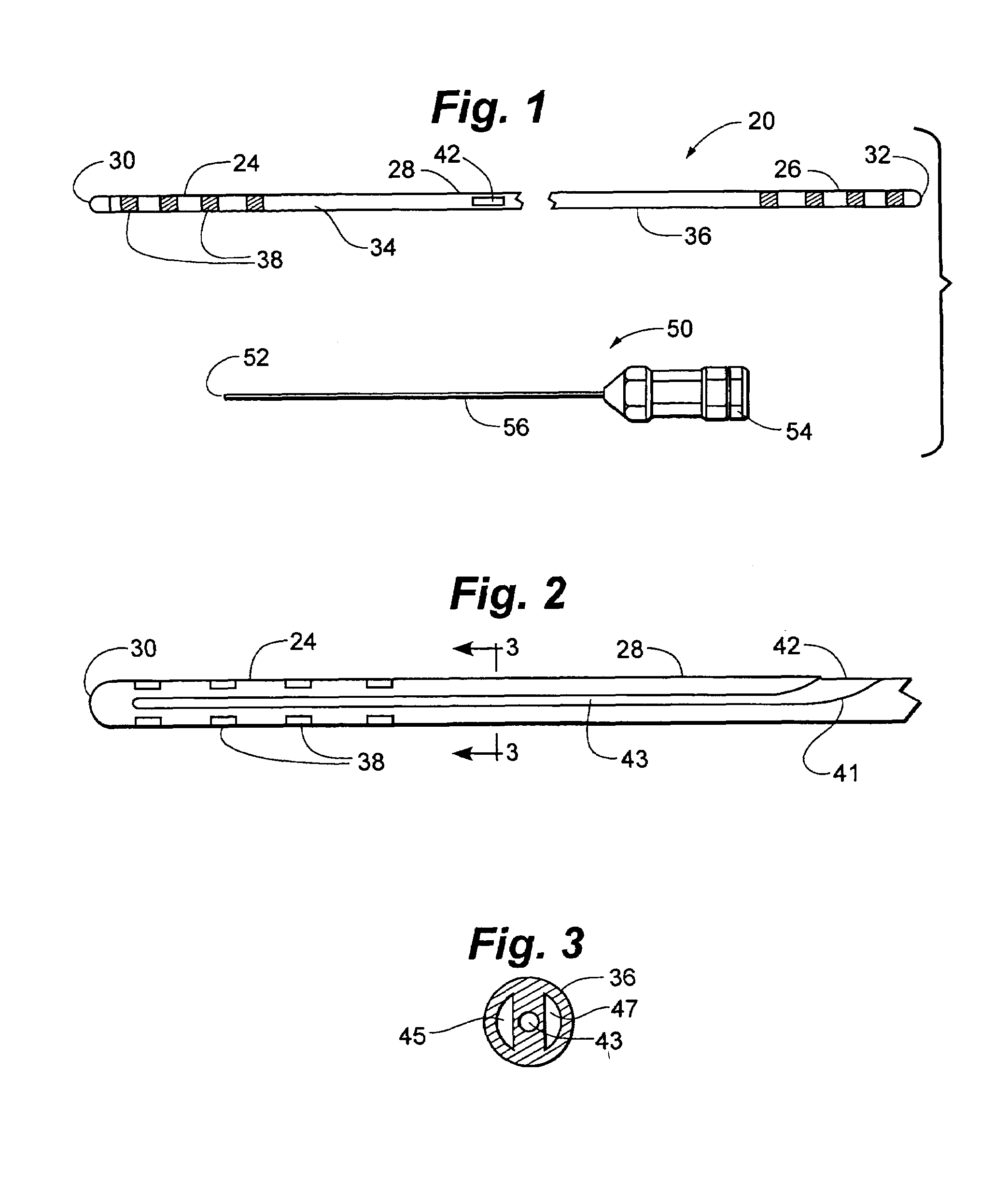
[0039]FIG. 1 illustrates a neurological stimulation lead 20 having a distal region 24, a proximal region 26, and an immediate region 28 disposed between the distal and proximal regions. In a preferred embodiment, the intermediate region is defined to lie between the innermost distal and proximal electrical contacts described below. A stylet entrance or insertion part 42 may be seen in intermediate region 28. Lead 20 can be formed of a body or shaft 34 extending between a distal end 30 and a proximal end 32. Lead body 34 has an exterior surface or tubular side wall 36. Lead body 34 is preferably formed of a polymeric material, for example, polyurethane or silicone.

[0040]Lead distal region 24 may include a number of electrodes 38, which may, for example, be disposed concentrically about lead body 34 in a spaced-apart configuration. Electrodes 38 may also be described as electrical contacts or contacts. Electrodes 38 are normally adapted to be inserted into the human body, are external...


PUM


Abstract

Implantable medical leads, lead assemblies, and methods for implanting the leads into the human body, for example, for use within the epidural spaces of the spinal column to manage pain. A stylet lumen extends within the lead between a side-wall stylet entrance port and a lead distal region. In use, exemplary stylets may be inserted through the lead stylet port to stiffen only the distal portion of the lead, and the distal portion of the lead inserted through an introducer needle into the human body. The stiffened distal portion of the lead may be short and easily controllable.

Description

RELATED APPLICATIONS[0001]This application is a continuation-in-part of U.S. patent application Ser. No. 10 / 423,179, filed Apr. 25, 2003, now abandoned, which is incorporated herein by reference in its entirety.FIELD OF THE INVENTION[0002]This application relates generally to medical leads, and more specifically to implantable, electrical neurological leads.BACKGROUND OF THE INVENTION[0003]Implantable leads having externally exposed ring or band electrodes can be used to deliver electrical stimulation to surrounding tissue and / or to sense electrical energy produced by the surrounding tissue. Such leads are often implanted, for example, within the epidural or intrathecal spaces of the spinal column, along peripheral nerves, within the brain, and about the heart. Electrical stimulation of the spinal cord has been shown to be effective in relieving intractable pain in some patients. Such electrical stimulation can reduce or eliminate the use of pain relieving drugs.[0004]One such lead ...

Claims


Application Information

Patent Timeline
Patent Type & Authority Patents(United States)
IPC IPC(8): A61N1/00A61N1/05
CPCA61N1/0529A61N1/0551A61N1/0558
Inventor SAGE, SHAHN S.HERNANDEZ, JOSE M.
Owner MEDTRONIC INC
Learn More