Observation apparatus

a technology of observation apparatus and observation image, which is applied in the field of improvement of observation apparatus, can solve the problems of deteriorating sharpness of observation image, inability to observe the surroundings of the fundus er (fundus surroundings) inability to observe the surroundings of the eye to be operated without changing the structure of the apparatus, etc., and achieves the effect of removing astigmatism

Inactive Publication Date: 2008-03-18
KK TOPCON
View PDF20 Cites 1 Cited by
  • Summary
  • Abstract
  • Description
  • Claims
  • Application Information

AI Technical Summary

Benefits of technology

[0028]The present invention has been made in view of the above circumstances. An object of the present invention is to provide an observation apparatus capable of suitably removing astigmatism that occurs when a state of an eye including a fundus and a vitreous body is observed.
[0029]Another object of the present invention is to provide an observation apparatus capable of suitably removing chromatic aberration that occurs when the state of the eye is observed.

Problems solved by technology

According to such an operation microscope apparatus, it is possible to observe the anterior ocular segment of the eye to be operated E. However, it is impossible to observe the surroundings of a fundus Er (fundus surroundings) of the eye to be operated E without changing the structure of the apparatus.
Therefore, the sharpness of the observation image deteriorates.
Therefore, when the fundus surroundings further apart from the fundus Er are observed, the sharpness of the observation image further deteriorates.
As described above, when the aberration amounts of the images observed by the right and left eyes are different from each other, it is hard for the operator to normally stereoscopically view the image of the fundus surrounding Er′.
The above-mentioned problem related to the astigmatism affects the case where coagulation treatment is performed on the fundus surroundings using laser light with the optical member such as the prism having the deflective action put to the cornea.
Even when the above-mentioned front lens is put between the eye to be operated and the objective lens, the problems related to the astigmatism and the chromatic aberration occur.

Method used


Image

  • Observation apparatus
  • Observation apparatus
  • Observation apparatus

Examples


first embodiment

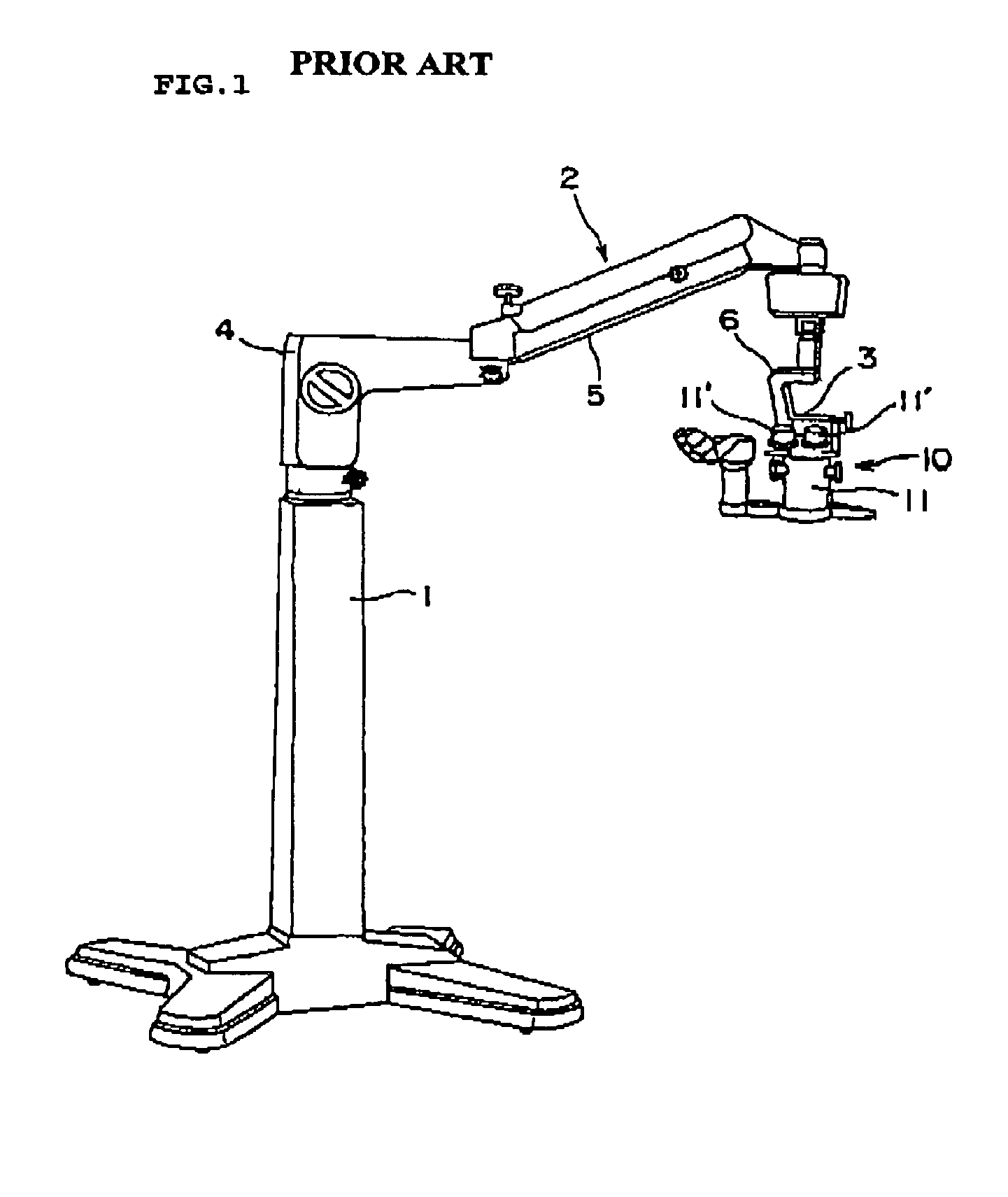
[0099]An operation microscope apparatus (observation apparatus) according to this embodiment has the external structure as shown in FIG. 1. Optical systems as shown in FIGS. 6 and 7 are disposed inside a lens barrel 11 of an operation microscope 10. In FIGS. 6 and 7, for descriptions the same references are provided to the same structural elements as in FIGS. 2 and 3, unless otherwise pointed out. In FIGS. 6, and 7, an auxiliary observation optical system for an operator's assistant is not shown. However, the auxiliary observation optical system can be provided by changing the structure of an optical system as appropriate. On the other hand, the structural elements different from those in FIGS. 2 and 3 will be intensively described below.

Structure of Optical System

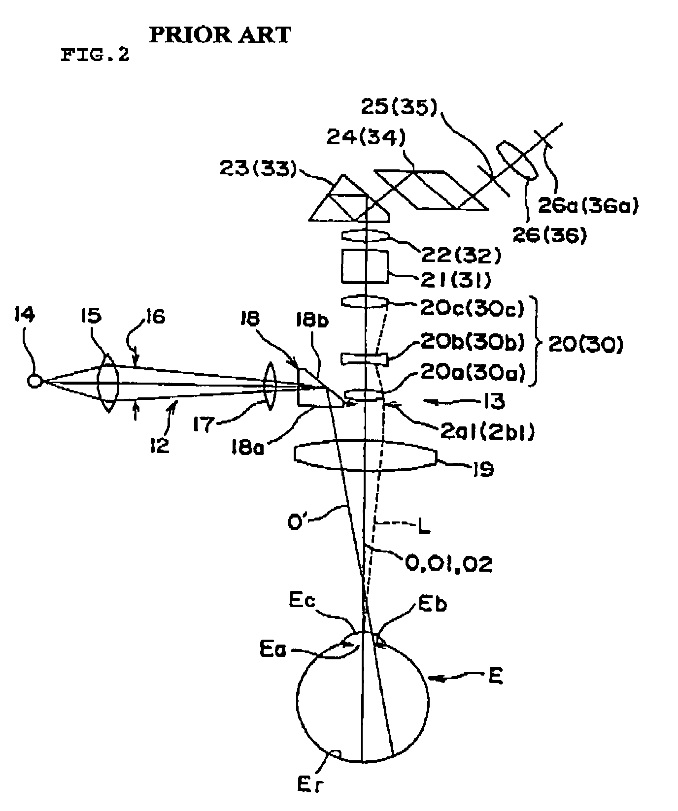
[0100]In the left observation optical system 13a, an observation optical path for relaying reflection light on a fundus Eras a parallel light flux to a variable lens system 20 is formed between an objective lens 19 and the...

second embodiment

[0147]Hereinafter, an observation apparatus according to a second embodiment of the present invention will be described. Note that the same references are provided to the same structural elements as in the first embodiment for the description.

Structure

[0148]The observation apparatus according to this embodiment includes the same optical systems as the observation apparatus according to the first embodiment. The same control panel 100 is provided on the observation apparatus according to this embodiment.

[0149]FIG. 19 is a block diagram showing a structure of a control system of the observation apparatus according to this embodiment. The image processing apparatus 64 shown in FIG. 19 includes the control unit 641, a memory 644, and a calculating unit 645. The control unit 641 has the same function as in the first embodiment. The memory 644 is a memory unit such as a ROM or a hard disk drive in the present invention and stores information as shown in FIG. 20 later. Note that the memory...

third embodiment

[0171]Hereinafter, an observation apparatus according to a third embodiment of the present invention will be described. The observation apparatus described in this embodiment has a structure for canceling a chromatic aberration caused when the contact prism or the like is put to the eye to be operated. Note that the same references are provided to the same structural elements as described above.

Structure

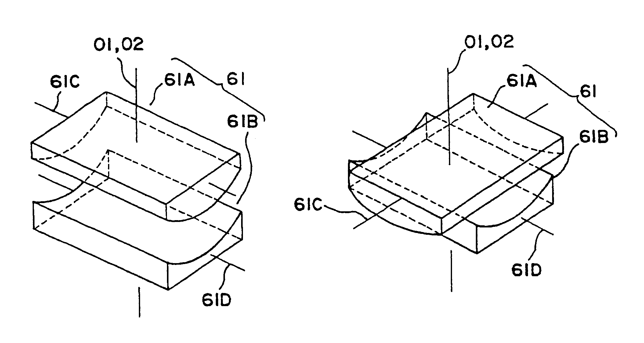
[0172]FIGS. 23 and 24 show a structure of an optical system of the observation apparatus according to this embodiment, which is substantially the same structure as the observation apparatus of the modified example of the first embodiment as shown in FIG. 18. More specifically, the observation apparatus according to this embodiment includes achromatic aberration canceling optical element 70 which is provided in each of the left and right observation optical systems 13a and 13b, instead of providing the astigmatism canceling optical element 61 shown in FIG. 18.

[0173]The chromatic aberr...


PUM


Abstract

An observation apparatus is provided. An apex angle of a contact prism is inputted by operating an apex angle setting knob of a control panel. A fining angle of the contact prism is inputted by operating a fitting angle setting knob. A control unit determines the amount of correction for astigmatism of a left observation optical system and the amount of correction for astigmatism of a right observation optical system based on a recognized observation magnification and the inputted apex angle. An axial angle for the astigmatism of the left observation optical system and an axial angle for the astigmatism of the right observation optical system are determined based on the inputted fitting angle. Variable cross cylinder lens rotating drive units are controlled to rotate cylinder lenses of each of the right and left observation optical systems, thereby obtaining the determined axial angle and the determined amount of correction.

Description

BACKGROUND OF THE INVENTION[0001]1. Field of the Invention[0002]The present invention relates to an improvement of an observation apparatus such as an operation microscope apparatus or a slit lamp microscope apparatus, and more particularly to an observation apparatus capable of removing astigmatism and chromatic aberration which occur when a state of an eye is observed.[0003]2. Description of the Related Art[0004]Up to now, there has been widely known an observation apparatus such as an operation microscope apparatus used for observing an eye which undergoes an operation (hereinafter referred to as “an eye to be operated”) (see JP 2003-062003A, specification paragraphs [0029] to [0032], FIGS. 4, 5, and 9) or a slit lamp microscope apparatus used for observing the anterior ocular segment and fundus portion of an eye to be examined (see JP 2001-037726 A, specification paragraphs [0017] to [0020], FIG. 1).[0005]Hereinafter, such an observation apparatus, in particular, an operation mi...

Claims


Application Information

Patent Timeline
Patent Type & Authority Patents(United States)
IPC IPC(8): A61B3/10A61B3/00G02B21/20A61B3/12A61B3/13A61B19/00G02B15/14
CPCA61B3/132
Inventor NODA, TORUONUMA, KAZUHIKOFUKUMA, YASUFUMINISHIO, KOJIAEBA, HIDETAKAOKAZAKI, YOSHIOSATO, MASARUKATO, YASUO
Owner KK TOPCON
Why Eureka
Try Eureka