Clot removal device

a clot removal and device technology, applied in the field of intravascular medical devices, can solve the problems of serious tissue damage, clots may lodge in blood vessels, and patients cannot immediately dissolve clots from patients,

Inactive Publication Date: 2008-03-18
STRYKER CORP +1
View PDF34 Cites 113 Cited by
  • Summary
  • Abstract
  • Description
  • Claims
  • Application Information

AI Technical Summary

Problems solved by technology

At other times, however, such clots may lodge in a blood vessel where they can partially or completely occlude the flow of blood.
If the partially or completely occluded vessel feeds blood to sensitive tissue such as, the brain, lungs or heart, for example, serious tissue damage may result.
These drugs, however, do not immediately dissolve the clot from the patient.

Method used


Image

  • Clot removal device
  • Clot removal device
  • Clot removal device

Examples


Embodiment Construction

[0011]The following description should be read with reference to the drawings wherein like reference numerals indicate like elements throughout the several views. The detailed description and drawings illustrate example embodiments of the claimed invention.

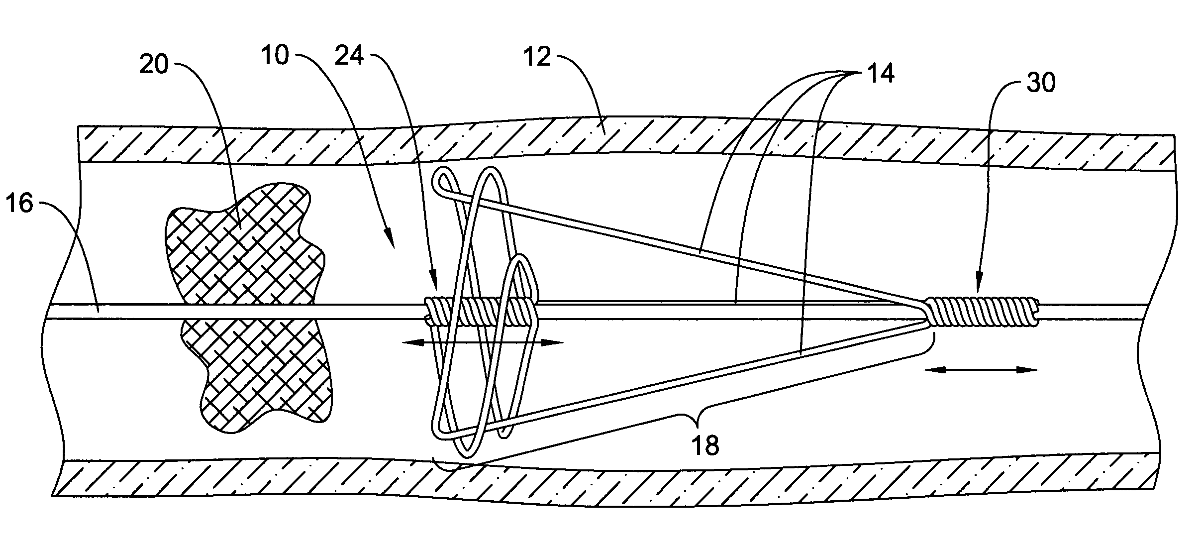
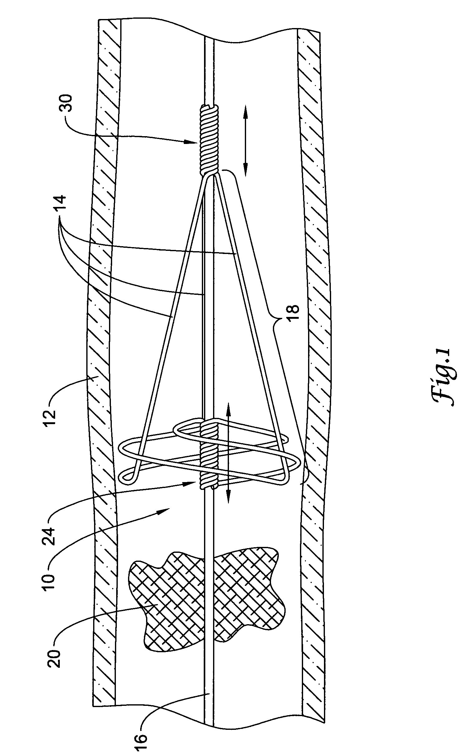
[0012]For a number of reasons, it may be desirable to capture and / or remove clots from the vasculature. FIG. 1 is a partial cross-sectional side view of an example clot pulling medical device 10 disposed in a blood vessel 12. Blood vessel 12 can be essentially any vessel. Device 10 may include a plurality of struts 14 coupled to an elongate shaft or guidewire 16. Struts 14 may define a basket member or region 18, suitable for capturing a blood clot 20 disposed in the vasculature. In general, device 10 can be advanced through the vasculature to a suitable location, for example adjacent clot 20, and configured so that clot 20 can be captured in basket region 18. Device 10 and the captured clot 20 can be removed from the vasculature....


PUM


Abstract

A device for removing blood clots and methods of making and using the same. The clot pulling device may include a shaft and one or more strut members that each may include a loop region. The proximal ends of the strut members may be attached to the shaft and the distal ends of the strut members may be coupled to the shaft.

Description

FIELD OF THE INVENTION[0001]The present invention pertains to intravascular medical devices. More particularly, the present invention pertains to devices for capturing and removing blood clots from a blood vessel.BACKGROUND[0002]The present invention pertains generally to emboli collection and removal.[0003]Blood thrombus, may form a clot in a patient vasculature. Sometimes such clots are harmlessly dissolved in the blood stream. At other times, however, such clots may lodge in a blood vessel where they can partially or completely occlude the flow of blood. If the partially or completely occluded vessel feeds blood to sensitive tissue such as, the brain, lungs or heart, for example, serious tissue damage may result.[0004]When symptoms of an occlusion are apparent, such as an occlusion resulting in a stroke, immediate action should be taken to reduce or eliminate resultant tissue damage. One approach is to treat a patient with clot dissolving drugs. These drugs, however, do not immed...

Claims


Application Information

Patent Timeline
Patent Type & Authority Patents(United States)
IPC IPC(8): A61M29/00A61B17/22
CPCA61B17/221A61B2017/2212A61B2017/2215
Inventor CARRISON, HAROLD F.FARNHOLTZ, ROGER
Owner STRYKER CORP
Why Eureka
Try Eureka