
Light diffusing member

a light diffusing member and light technology, applied in the field of light diffusing members, can solve the problems of inability to achieve satisfactory surface protective effect and inability to achieve anti-reflection effect, and achieve excellent light diffusing effect and anti-reflection effect. , the effect of satisfying the surface protective

Active Publication Date: 2008-03-18
DAI NIPPON PRINTING CO LTD
View PDF12 Cites 3 Cited by
  • Summary
  • Abstract
  • Description
  • Claims
  • Application Information

AI Technical Summary

Benefits of technology

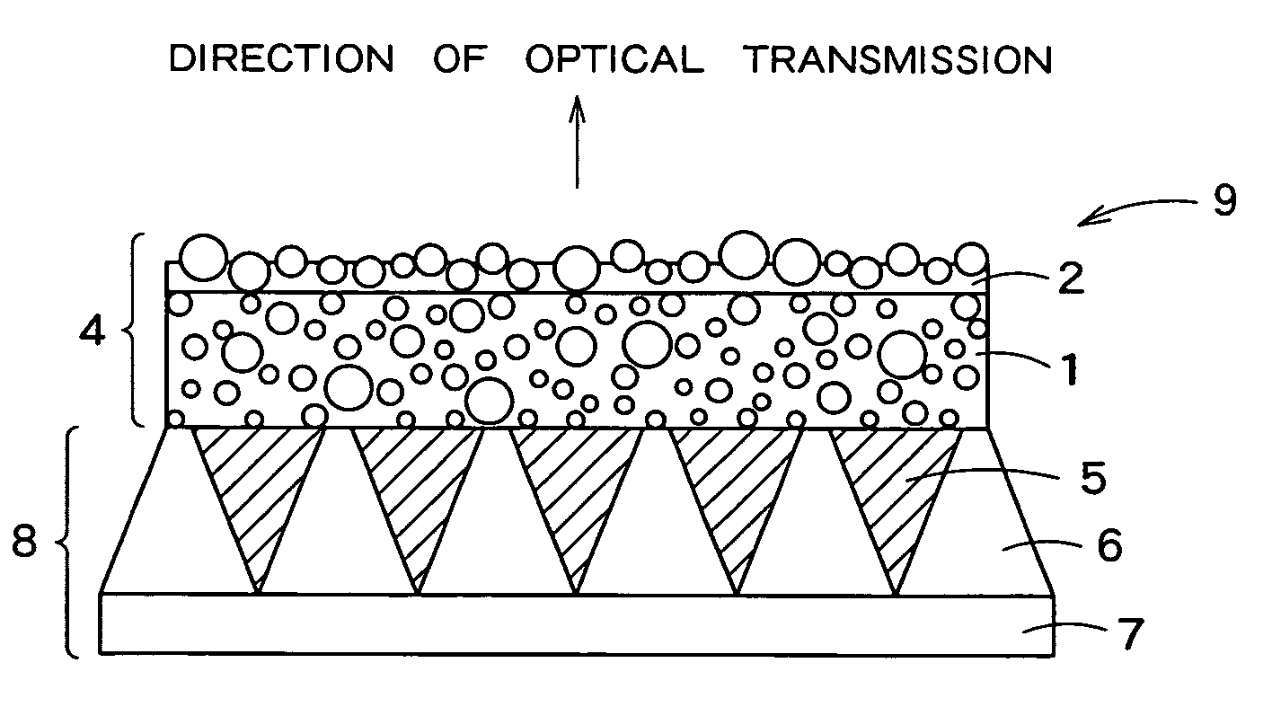
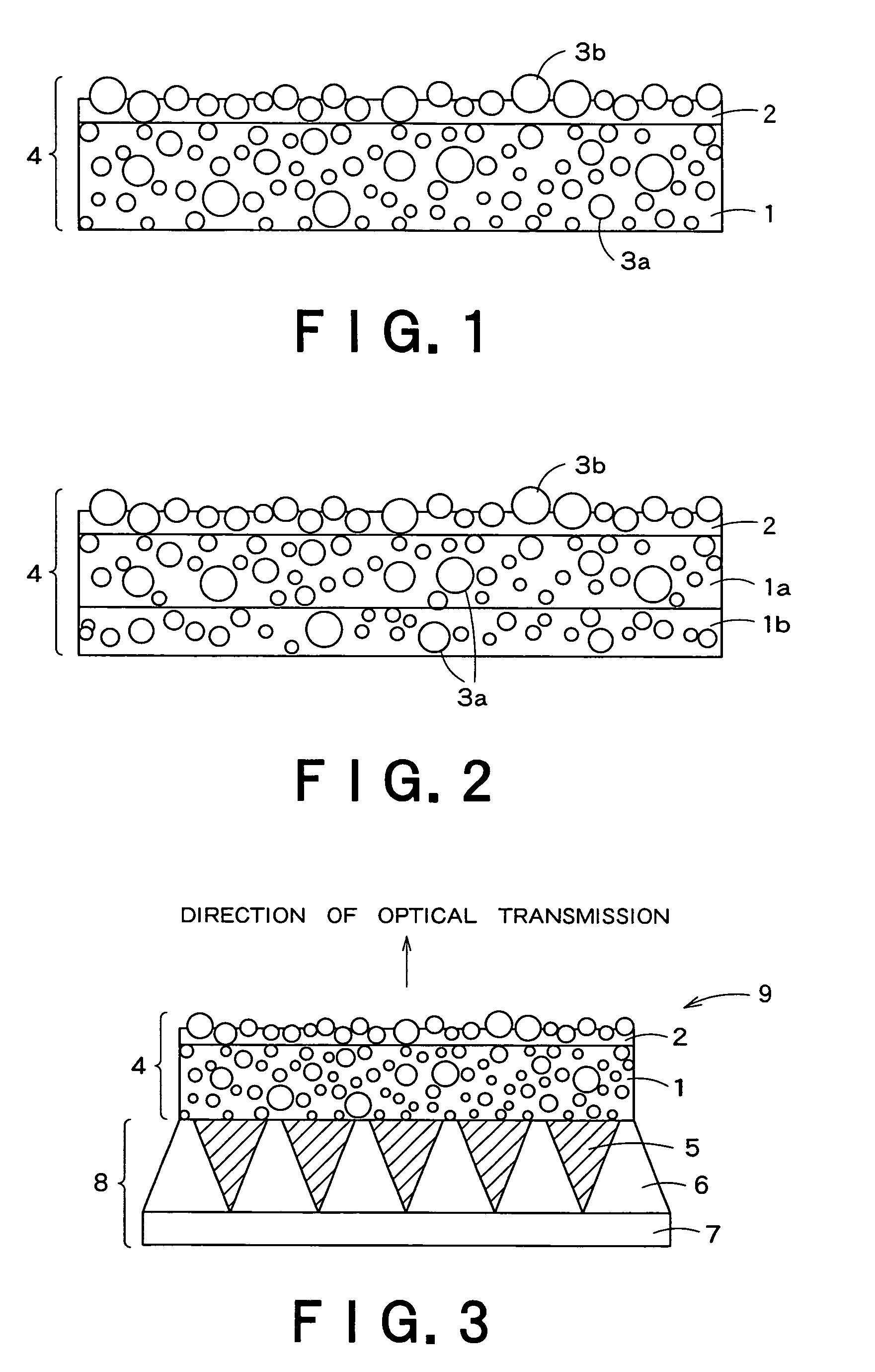
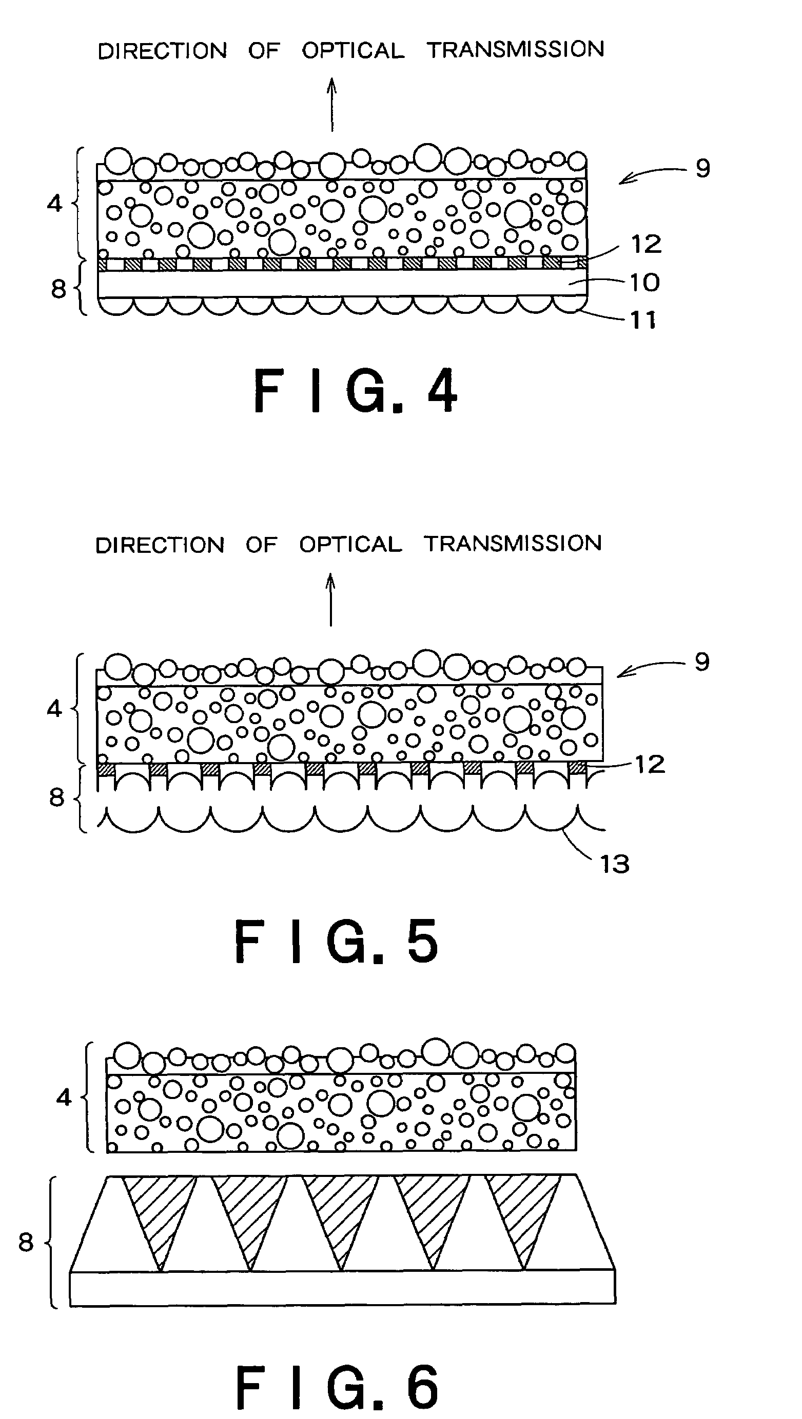
The present invention provides a light diffusing member for a transmission screen that has excellent light diffusing and antireflection effects while also having a satisfactory surface protective effect. This is achieved by providing a hard coat layer with fine particles on a substrate, where the fine particles are projected on the surface of the hard coat layer to constitute concaves and convexes. The hard coat layer has a thickness satisfying a certain requirement and contains fine particles with a predetermined particle diameter. This simultaneously realizes internal diffusion (light effusing effect) and surface diffusion (antireflection effect) and further protects the surface of the screen. The invention also provides an optical member for a transmission screen comprising the light diffusing member and a horizontal angle-of-view expanding member, which further enhances the surface protective effect and antireflection effect. Additionally, the invention provides a transmission screen comprising the optical member and a Fresnel lens member, which further improves the image quality and reduces the harshness of the projected images.

Problems solved by technology

The provision of a protective layer (also known as a hard coat layer) on the surface of the light diffusing plate for screen surface protection purposes, however, has posed a problem that the concaves and convexes on the surface of the light diffusing plate disappear making it impossible to attain the antireflection effect.
On the other hand, when an attempt is made to provide a protective layer in such a thickness that exhibits the antireflection effect, the thickness of the protective layer should be around the level of concaves and convexes on the surface of the light diffusing plate, that is, should be smaller than the particle diameter of the transparent fine particles, posing a problem that satisfactory surface protective effect cannot be attained.

Method used


Image

  • Light diffusing member
  • Light diffusing member
  • Light diffusing member

Examples


production example 1

[0050]Five types of resin beads having average particle diameters of 3 μm, 5 μm, 10 μm, 15 μm, and 18 μm were used. All of these resin beads were of a monodisperse type and had a standard deviation of 3 μm. The resin beads were mixed in the ultraviolet curing resin composition to a concentration of 3% by weight to prepare coating liquids.

[0051]Each of the coating liquids was then dip coated onto the substrate. The coating was irradiated with ultraviolet light to cure the resin composition and thus to form a hard coat layer on a surface of the substrate. Thus, a light diffusing member was prepared. The thickness of the hard coat layer was regulated by regulating the speed of pulling up the substrate from the coating liquid in the formation of the hard coat layer by dip coating. Light diffusing members were prepared in the same manner as described above, except that the thickness of the hard coat layer was varied.

[0052]The thickness of the hard coat layer, and the average particle dia...

production example 2

[0054]Resin beads, which were of a monodisperse type and had an average particle diameter of 10 μm and a standard deviation of 3 μm, were used. The resin beads were mixed in the ultraviolet curing resin composition to the content (% by weight) specified in Table 2 below to prepare coating liquids.

[0055]Each of the coating liquids was then dip coated onto a surface of the substrate. The coating was irradiated with ultraviolet light to cure the resin composition and thus to form a hard coat layer on the surface of the substrate. In this case, the thickness of the hard coat layer was regulated to 10 μm by regulating the speed of pulling up the substrate from the coating liquid. Thus, light diffusing members with varied resin bead contents were prepared.

[0056]The thickness of the hard coat layer, and the average particle diameter, content and standard deviation of the resin beads used were as specified in Table 2.

[0057]

TABLE 2SubstrateHard coat layerAverageAverageparticleparticleStandar...

production example 3

[0058]Two types of resin beads with varied standard deviations were provided. Both the resin beads had an average particle diameter of 10 μm. The resin beads were mixed in the ultraviolet curing resin composition to a concentration of 3% by weight to prepare coating liquids. Each of the coating liquids was coated onto a surface of the substrate in the same manner as in Production Example 2 to form a hard coat layer. In the same manner as in Production Example 2, the thickness of the hard coat layer was regulated to 10 μm. Thus, light diffusing members with varied resin bead contents were prepared.

[0059]The thickness of the hard coat layer, and the average particle diameter, content and standard deviation of the resin beads used were as specified in Table 3.

[0060]

TABLE 3SubstrateHard coat layerAverageAverageparticleparticleStandardContentThicknessdiameter ofdiameter ofdeviationof resinof hardProductionresin beads,resin beads,of resinbeads,coat layer,Example 3μmμmbeads, μmwt %μmC11010...


PUM

PropertyMeasurementUnit
particle diameteraaaaaaaaaa
particle diametersaaaaaaaaaa
particle diameteraaaaaaaaaa

Abstract

There is provided a light diffusing member for a transmission screen that has a satisfactory surface protective effect while maintaining excellent light diffusing effect and antireflective effect. The light diffusing member for a transmission screen comprises a hard coat layer provided on a surface of a substrate having a single-layer or multilayer structure, wherein fine particles are contained in the substrate and the hard coat layer, and the average particle diameter of the fine particles contained in the hard coat layer is 5 to 15 μm, the hard coat layer has a thickness satisfying a requirement represented by formula (d−2)≦t≦d wherein t represents the thickness of the hard coat layer, μm; and d represents the average particle diameter of the fine particles, μm, and a part of the fine particles is projected on the surface of the hard coat layer to constitute concaves and convexes.

Description

BACKGROUND OF THE INVENTION[0001]1. Field of the Invention[0002]The present invention relates to a light diffusing member for a transmission screen for use in transmission projection televisions and the like, and an optical member and a transmission screen using the light diffusing member.[0003]2. Background Art[0004]Transmission projection televisions are display devices for enlarging and projecting images from light sources such as CRTs, liquid crystal projectors, or DLPs on a transmission screen. In such display devices, a light diffusing plate or the like for diffusing outgoing light is provided on the surface of the screen to reduce dazzling at the time of visual observation of the screen. Further, in order to reduce a deterioration in visibility of the projected image caused by external light-derived dazzling on the screen surface, an antireflection film is sometimes provided on the screen surface. As disclosed, for example, in Japanese Patent Laid-Open Nos. 295818 / 1999 and 28...

Claims


Application Information

Patent Timeline
Patent Type & Authority Patents(United States)
IPC IPC(8): G03B21/60G02B1/10G02B1/111G02B1/14G02B5/02G02F1/1335G03B21/62G03B21/625
CPCG03B21/625H04N5/74G03B21/62
Inventor BABA, SHIGEKIOTAKA, NORIHIKOUOTANI, YUKIFUMINAKANO, KOICHIHASHIMOTO, KOJI
Owner DAI NIPPON PRINTING CO LTD
Learn More