
Light guiding apparatus and light source device including the same

a technology of light guiding apparatus and light source device, which is applied in the direction of lighting and heating apparatus, fibre light guides, instruments, etc., can solve the problems of poor visual effect for users in the habit of tungsten-based light emitting devices, short life and high power loss rate, and achieve novel light emitting effects and good light uniformity

Inactive Publication Date: 2014-08-07
WINTEK CORP
View PDF3 Cites 5 Cited by
  • Summary
  • Abstract
  • Description
  • Claims
  • Application Information

AI Technical Summary

Benefits of technology

The present invention is a light source device with good light uniformity and a unique light emitting effect. It was designed to overcome the issue of uneven light scattering that was present in previous designs. This resulted in a light source device that was more efficient, uniform, and effective.

Problems solved by technology

Tungsten-based light-emitting mechanism, however, is very power-consumed, and it features short life and high power-loss rate.
However, merely relying on the design of the optical surfaces of the light guiding apparatus for distributing the light beams has a defect of uneven distribution, which likely causes noticeable bright lines occurred when such a light source device is close to a wall surface, and therefore, it causes a poor visual effect for a user in the habit of the tungsten-based light emitting device for long term already.
Thus, how to make a light guiding apparatus uniformly guide out the LED source and to increase the visual effect has become an issue to be primarily resolved in this field today.

Method used


Image

  • Light guiding apparatus and light source device including the same
  • Light guiding apparatus and light source device including the same
  • Light guiding apparatus and light source device including the same

Examples


Embodiment Construction

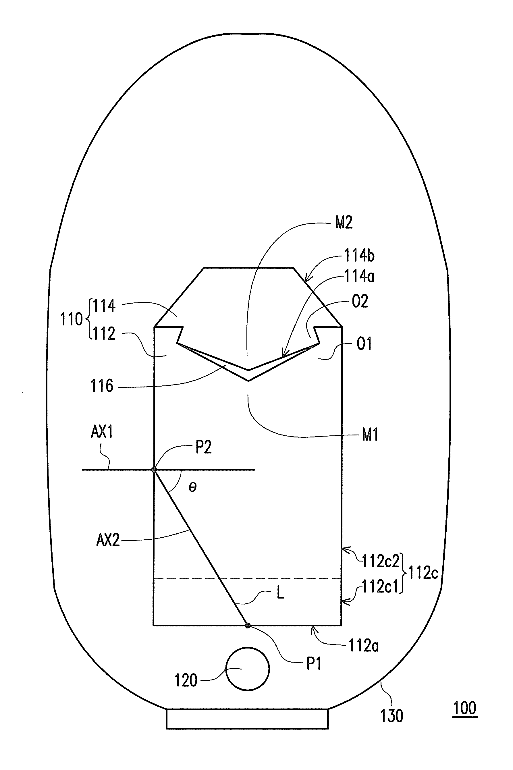
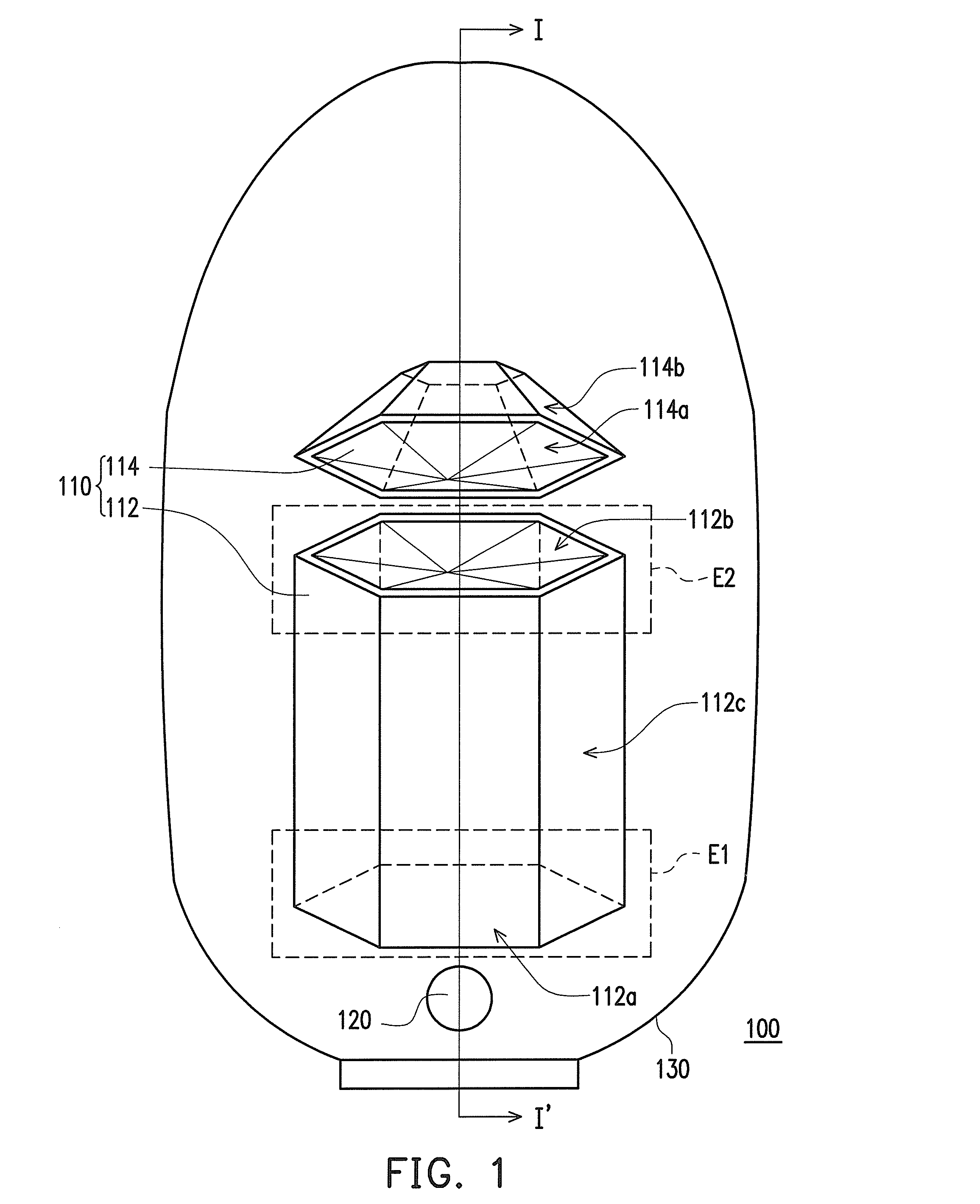
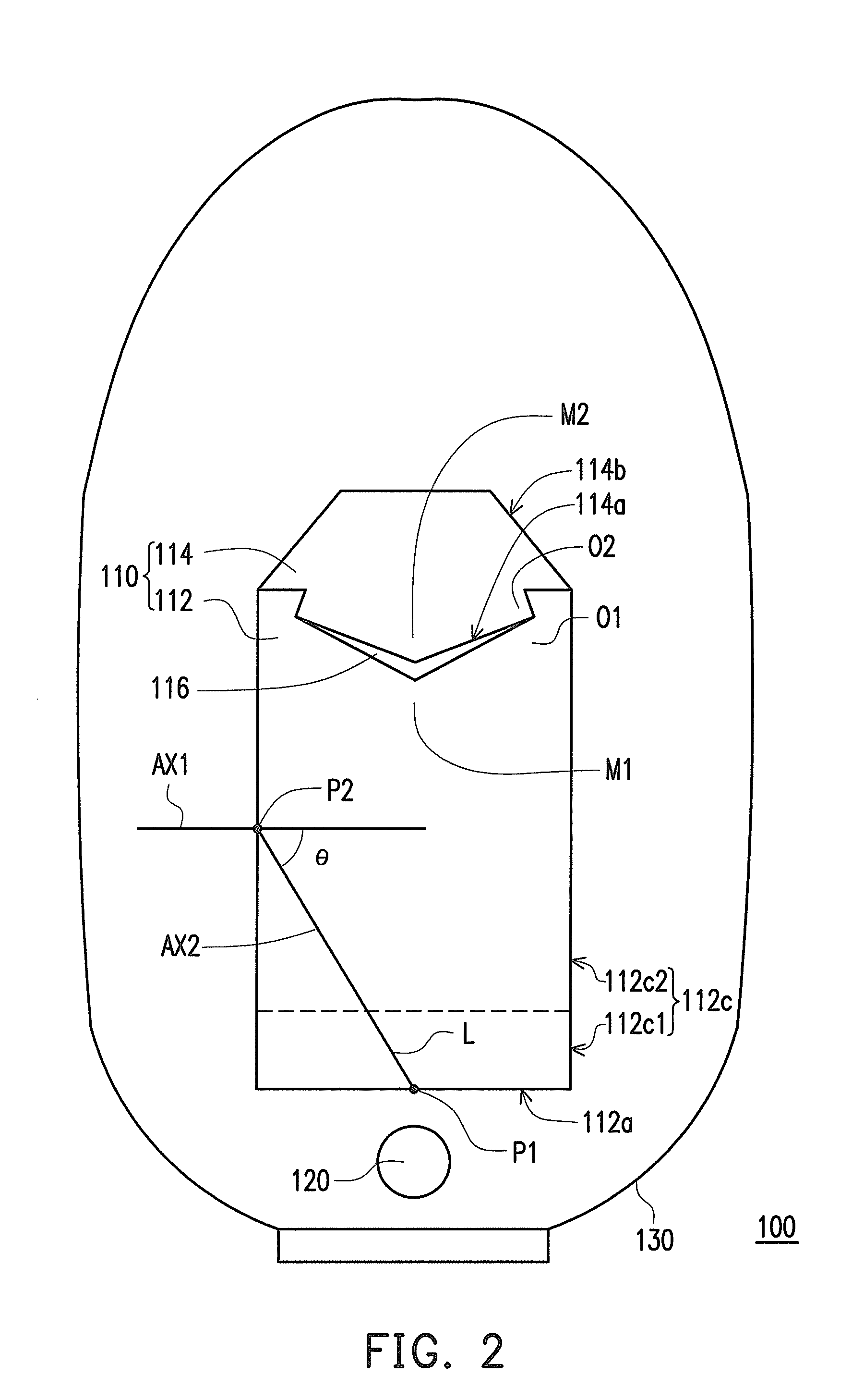
[0032]FIG. 1 is an exploded diagram of a light source device according to an embodiment of the invention and FIG. 2 is a cross-sectional diagram of FIG. 1 along I-I′. Referring to FIGS. 1 and 2, in the embodiment, a light source device 100 includes a light guiding apparatus 110, a light emitting element 120 and a lampshade 130. The light guiding apparatus 110 includes a first light guide 112 and a second light guide 114. The first light guide 112 includes a first end-surface E1, a second end-surface E2 and a side-surface 112c. The first end-surface E1 includes a first incident surface 112a thereon, the second end-surface E2 includes a first light emitting surface 112b thereon, and the side-surface 112c is located between the first end-surface E1 and the second end-surface E2 of the first light guide 112. The second light guide 114 has a second incident surface 114a and a second light emitting surface 114b connecting the second incident surface 114a, in which at least a partial regio...


PUM


Abstract

A light guiding apparatus includes a light guiding apparatus and a second light guide. The first light guide includes a first end-surface, a second end-surface and a side-surface, in which the first end-surface includes a first light incident surface thereon, the second end-surface includes a first light emitting surface thereon, and the side-surface is located between the first end-surface and the second end-surface of the first light guide. The second light guide has a second incident surface and a second light emitting surface connecting the second incident surface, in which at least a partial region of the second light emitting surface is a roughened surface, the second incident surface or the first light emitting surface is a roughened surface, and the second incident surface is corresponding to the first light emitting surface.

Description

CROSS-REFERENCE TO RELATED APPLICATION[0001]This application claims the priority benefit of Taiwan application serial no. 102202297, filed on Feb. 1, 2013. The entirety of the above-mentioned patent application is hereby incorporated by reference herein and made a part of this specification.BACKGROUND[0002]1. Field of the Utility Model[0003]The present invention generally relates to a light source device, and particularly, to a light source device having a light guiding apparatus.[0004]2. Description of Related Art[0005]A conventional light source device in a crystal lamp is designed according to the tungsten light source at the center of a lampshade. Tungsten-based light-emitting mechanism, however, is very power-consumed, and it features short life and high power-loss rate.[0006]In recent years, with the good development of the light emitting diode (LED) light source development, another option of the light source device is available, which can achieve power-saving and other chara...

Claims


Application Information

Patent Timeline
Patent Type & Authority Applications(United States)
IPC IPC(8): F21V8/00
CPCG02B6/0076G02B6/0008F21V2200/00F21K9/61
Inventor LIN, MING-CHUANHUANG, KUO-JUIYU, CHANG-WEILEE, HSIU-PINGCHEN, PING-YENG
Owner WINTEK CORP
Learn More