
Memory device with time-shifting based emulation of reference cells

a memory device and reference cell technology, applied in the field of memory, to achieve the effect of increasing the complexity of logic means

Inactive Publication Date: 2008-03-18
MICRON TECH INC
View PDF7 Cites 39 Cited by
  • Summary
  • Abstract
  • Description
  • Claims
  • Application Information

AI Technical Summary

Benefits of technology

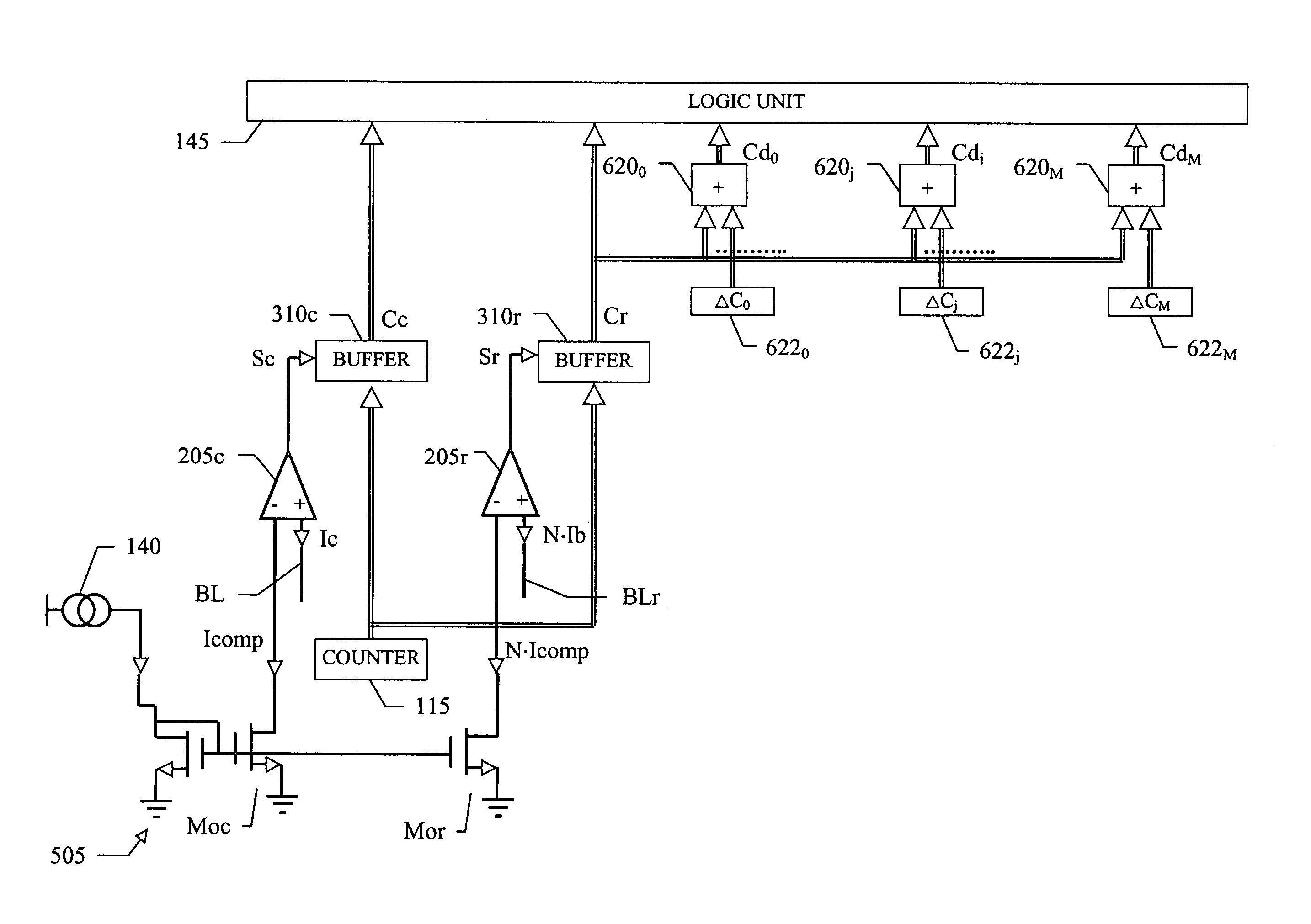
[0013]Indeed, it is possible to emulate any reference cell from an available one with a well-defined difference in their threshold voltages; particularly, any inaccuracy of the available reference cell only causes a change in the absolute values of the threshold voltages (of the same reference cell and of the emulated ones), but it is completely immaterial to their differences. In this way, the desired windows for discriminating the different conditions of the memory cells can be defined with a very high degree of precision.
[0031]This modular structure reduces the effects of a spread of the threshold voltage of the reference cell (since the differences among the threshold voltages of its basic elements substantially cancel on the average).

Problems solved by technology

Indeed, it is possible to emulate any reference cell from an available one with a well-defined difference in their threshold voltages; particularly, any inaccuracy of the available reference cell only causes a change in the absolute values of the threshold voltages (of the same reference cell and of the emulated ones), but it is completely immaterial to their differences.

Method used


Image

  • Memory device with time-shifting based emulation of reference cells
  • Memory device with time-shifting based emulation of reference cells
  • Memory device with time-shifting based emulation of reference cells

Examples


Embodiment Construction

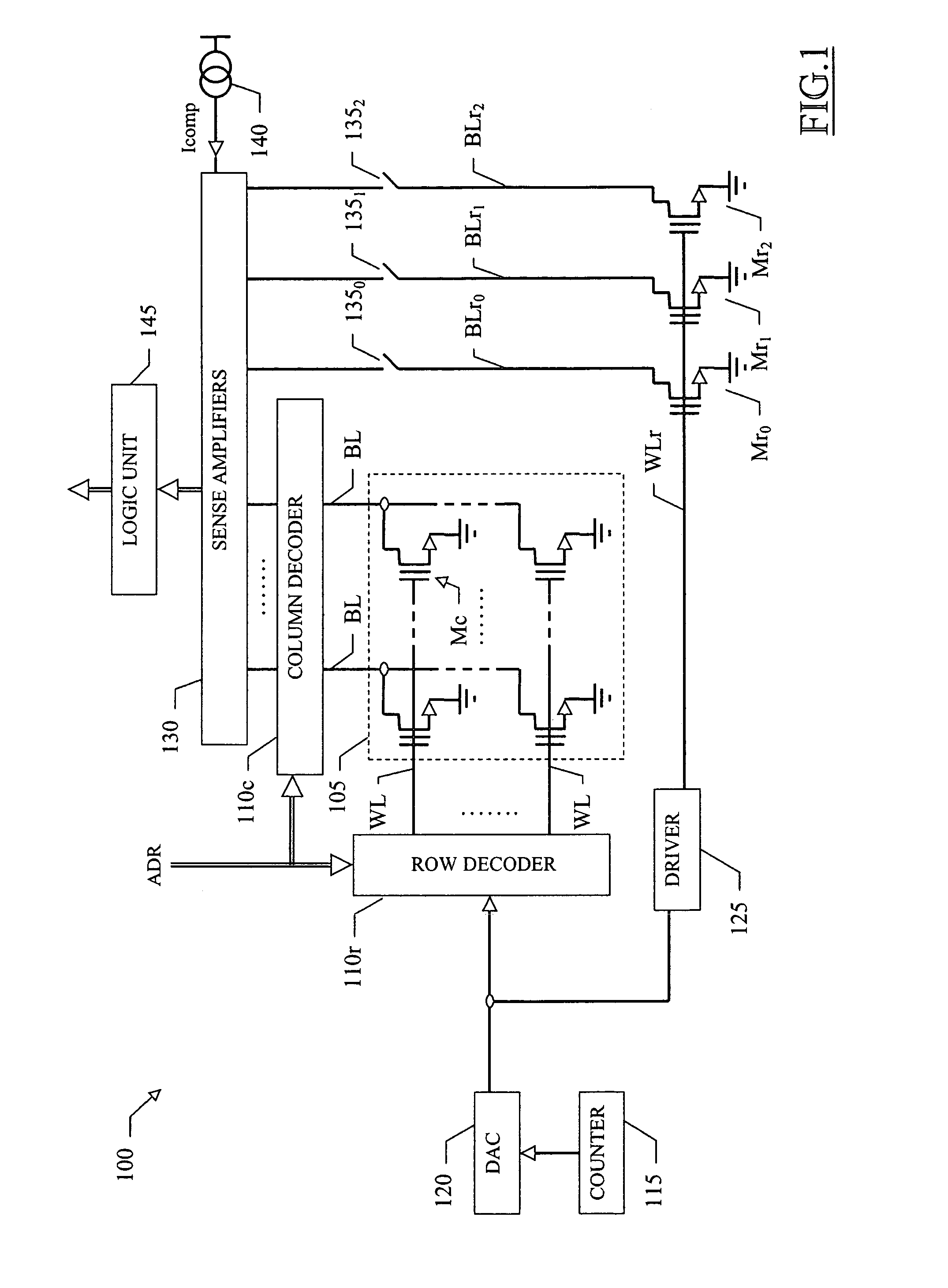
[0042]With reference in particular to FIG. 1, a non-volatile memory device 100 (for example, consisting of a flash E2PROM) is illustrated. The memory device 100 is integrated in a chip of semiconductor material, and includes a matrix 105 of memory cells Mc. Each memory cell Mc includes a floating gate MOS transistor with a programmable threshold voltage Vthc. The memory cell Mc in a non-programmed (or erased) condition exhibits a low threshold voltage. The memory cell Mc is programmed by injecting electric charge into its floating gate; the memory cell Mc can be programmed to multiple levels, each one associated with a corresponding range of its threshold voltage Vthc. Each level represents a different logical value; for example, the memory device 100 operates at 4 levels, so that each memory cell Mc stores a logical value consisting of 2 bits of information (11, 10, 01 and 00 for increasing threshold voltages Vthc).

[0043]The matrix 105 includes one or more sectors (only one shown i...


PUM


Abstract

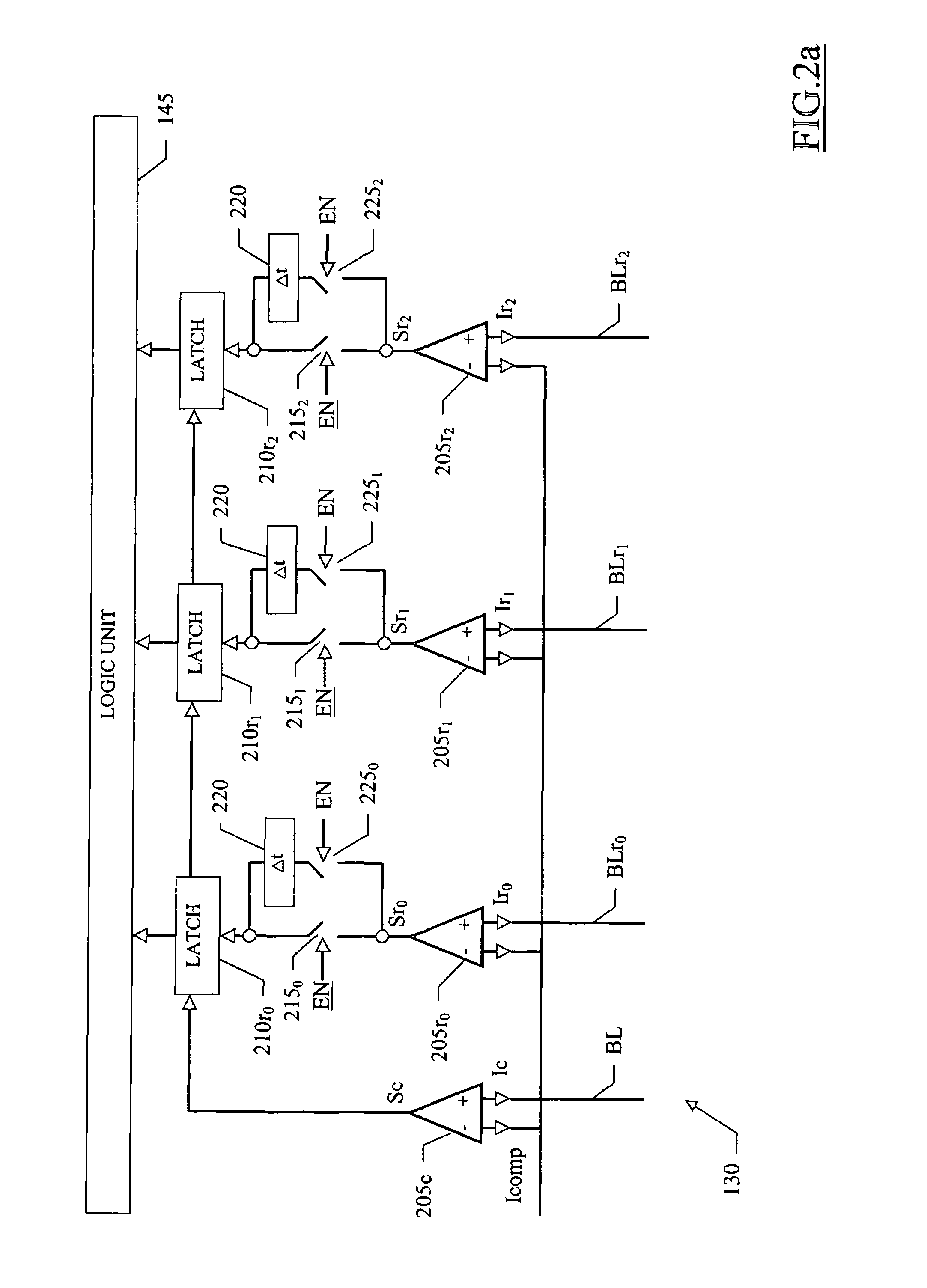
A memory device includes a plurality of memory cells and a comparison circuit that compares a set of selected memory cells with at least one reference cell having a threshold voltage. The comparison circuit includes a bias circuit that applies a biasing voltage having a substantially monotone time pattern to the selected memory cells and to the at least one reference cell, sense amplifiers that detect the reaching of a comparison current by a cell current of each selected memory cell and by a reference current of each reference cell, a logic unit that determines a condition of each selected memory cell according to a temporal relation of the reaching of the comparison current by the corresponding cell current and by the at least one reference current, and a time shift structure that time shifts at least one of said detections according to at least one predefined interval to emulate the comparison with at least one further reference cell having a further threshold voltage.

Description

BACKGROUND OF THE INVENTION[0001]1. Field of the Invention[0002]The present invention relates to the memory field. More specifically, the present invention relates to the reading of memory devices.[0003]2. Description of the Related Art[0004]Memory devices are commonly used to store information (either temporarily or permanently) in a number of applications; for example, in a non-volatile memory device the information is preserved even when a power supply is off. Typically, the memory device includes a matrix of memory cells (for example, consisting of floating gate MOS transistors); each memory cell has a threshold voltage that can be programmed to different levels representing corresponding logical values. Particularly, in a multi-level memory device each cell can take more than two levels (and then store a plurality of bits).[0005]The logical values stored in selected cells of the memory device are read by comparing a current flowing through each memory cell with the currents pro...

Claims


Application Information

Patent Timeline
Patent Type & Authority Patents(United States)
IPC IPC(8): G11C17/00
CPCG11C11/5642G11C16/32G11C2211/5634
Inventor PIO, FEDERICOBOLANDRINA, EFREMVIMERCATI, DANIELE
Owner MICRON TECH INC
Learn More