
Scheduling connections in a multi-stage switch to retain non-blocking properties of constituent switching elements

a multi-stage switch and scheduling algorithm technology, applied in the direction of data switching networks, electrical equipment, digital transmission, etc., can solve the problems of large switch operation at a very slow rate, large switch is too large to be economically used for large cross-connects, and none of the known scheduling algorithms provide non-blocking operation for unicast, etc., to and minimize the difference in the number of connections

Inactive Publication Date: 2008-03-18
INTEL CORP
View PDF38 Cites 5 Cited by
  • Summary
  • Abstract
  • Description
  • Claims
  • Application Information

AI Technical Summary

Benefits of technology

[0013]Embodiments of the invention include a scheduling algorithm that implements a method of scheduling connections in a multi-stage switch, resulting in less switching elements being required than known switching architectures to increase bandwidth and to retain the non-blocking properties of the constituent switching elements for incoming traffic, including multicast traffic. A scheduling algorithm is also provided that implements a method of incremental scheduling of connections being added or removed in a multi-stage switch, resulting in rapid reconfiguration of the switch due to a limited number of rearrangements that are required.
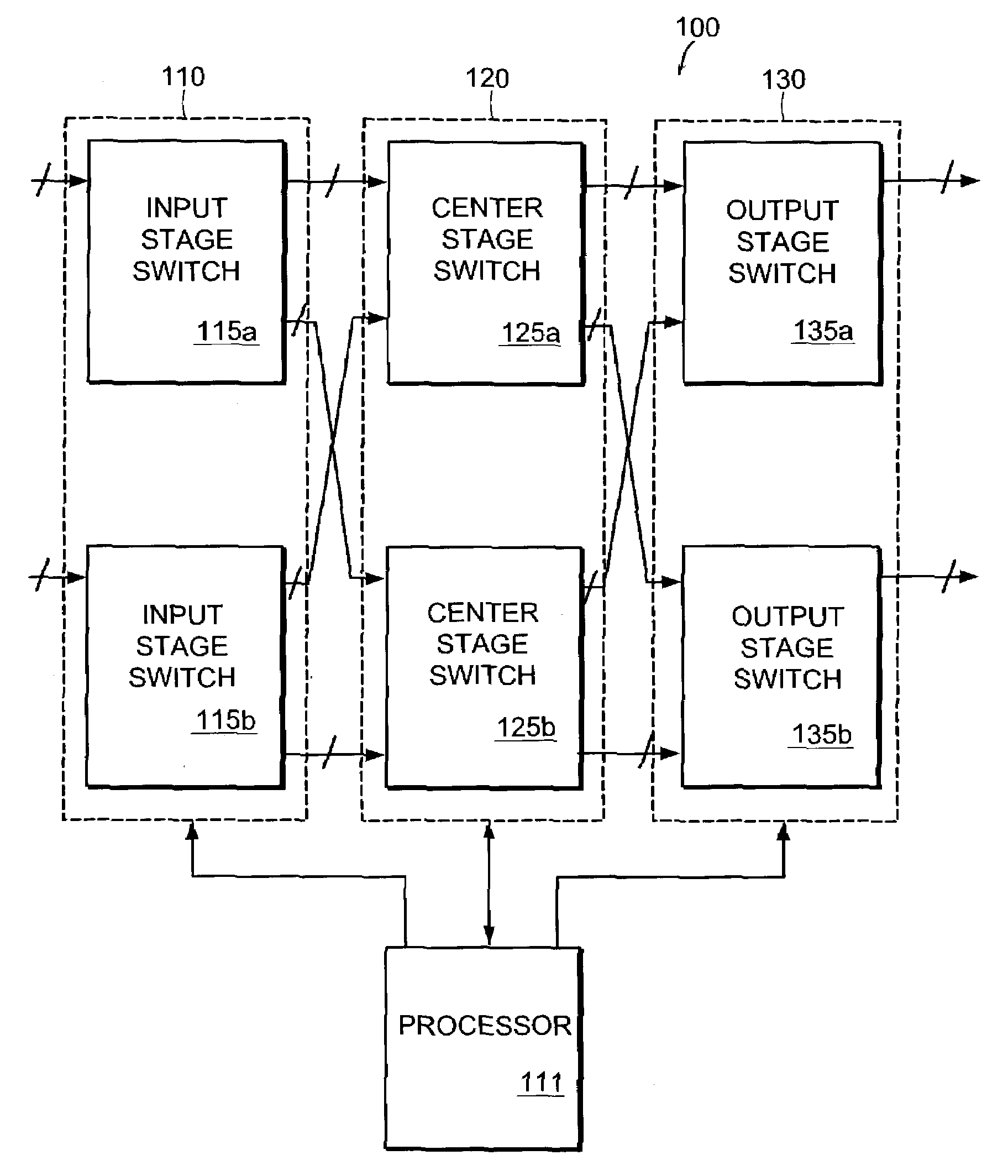
[0015]Such embodiments schedule a configured set of input / output connections including multicast connections between the two center stage switching elements according to a scheduling pattern in order to minimize the difference in the numbers of connections scheduled for the respective center stage switching elements that originate from a common input stage switching element and to minimize the difference in the numbers of connections scheduled for the respective center stage switching elements that are destined for a common output stage switching element. Such embodiments result in the non-blocking properties of the respective switching elements being retained, because substantially equal numbers of connections originating from each input stage switching element and destined for each output are scheduled between the two center stage switching elements. According to one embodiment, each difference being minimized is at most two connections.
[0023]When adding a new connection, such embodiments include adding the connection to a first configured set of input / output connections including multicast connections, resulting in a second configured set of input / output connections. Temporary schedules are then generated for the two center stage switching elements from the second configured set of input / output connections according to a scheduling pattern in order to minimize the difference in the numbers of connections scheduled for the respective center stage switching elements that originate from a common input stage switching element and to minimize the difference in the numbers of connections scheduled for the respective center stage switching elements that are destined for a common output stage switching element, resulting in the non-blocking properties of the respective switching elements being retained. Scheduled connections for the two center stage switching elements are then rearranged using a limited number of rearrangements, such as six, matching the temporary schedules.
[0024]When removing a connection, such embodiments include removing a connection from a first configured set of connections, resulting in a second configured set of connections. Existing schedules for the two center stage switching elements are then obtained. The existing schedules are previously generated by the processor according to a scheduling pattern in order to minimize the difference in the numbers of connections scheduled for the respective center stage switching elements that originate from a common input stage switching element and to minimize the difference in the numbers of connections scheduled for the respective center stage switching elements that are destined for a common output stage switching element, resulting in the non-blocking properties of the respective switching elements being retained. A scheduled connection is then removed from one of the existing schedules that corresponds to the removed connection. The existing schedules are then rearranged using a limited number of rearrangements, such as six, to minimize a difference between the schedules.

Problems solved by technology

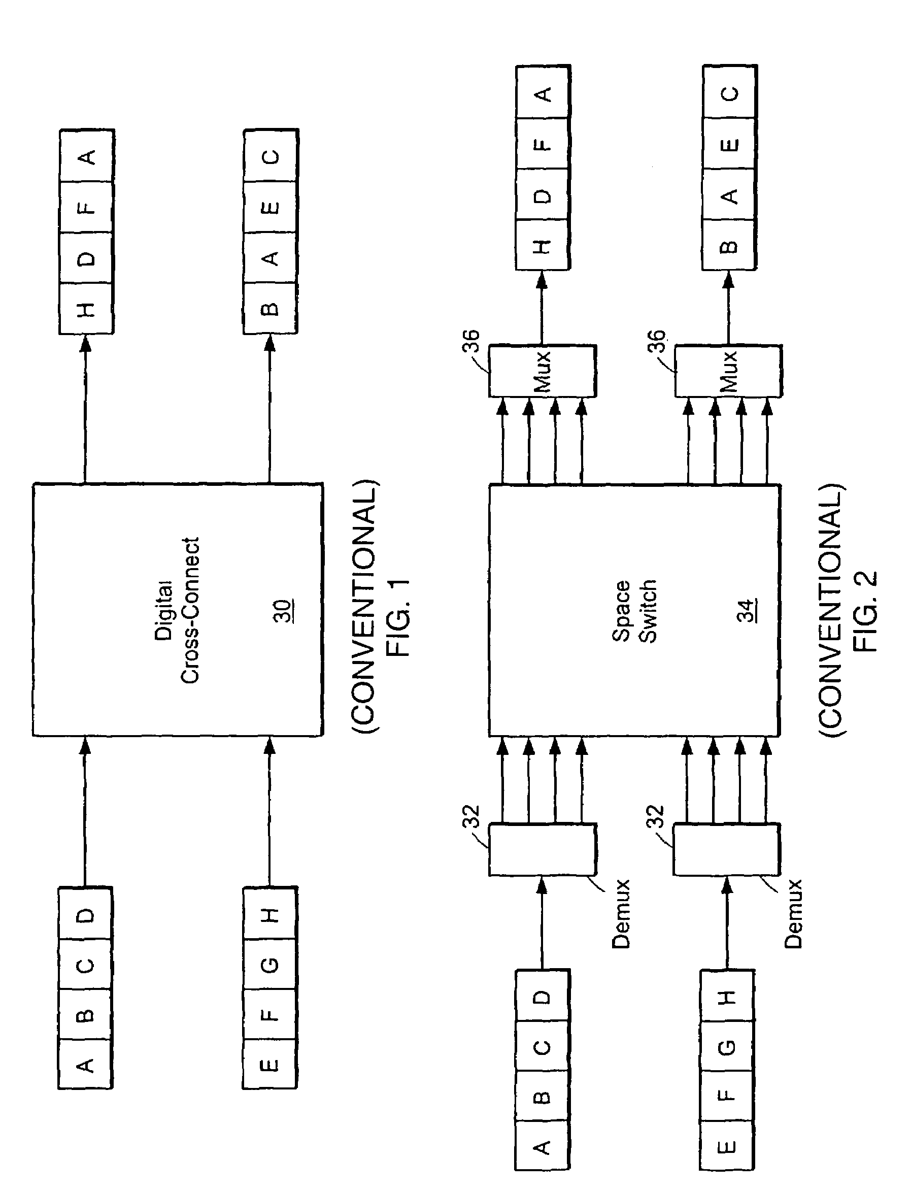
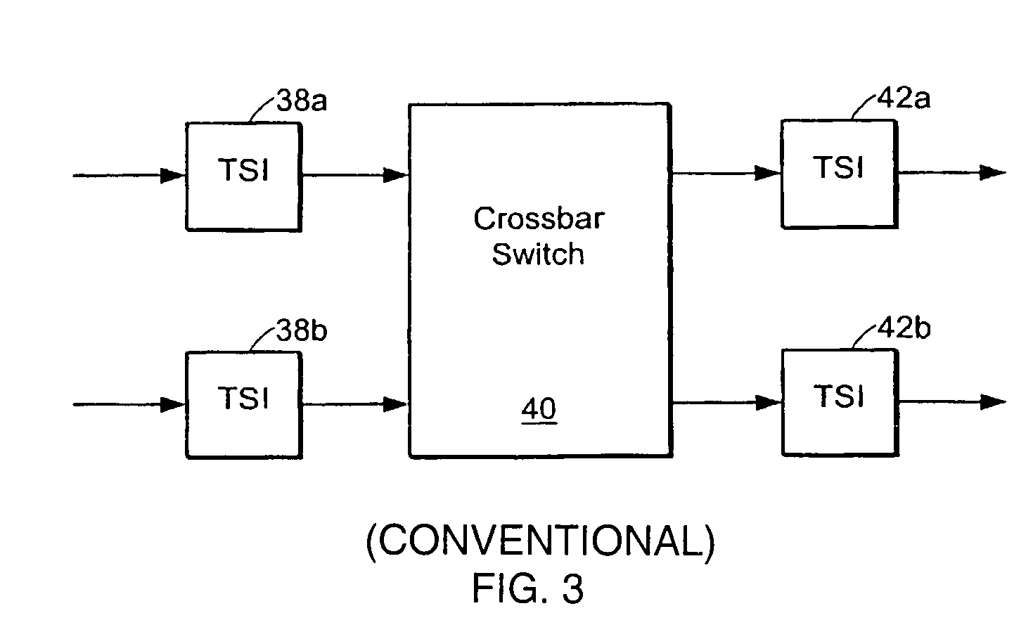
However, this space-switch architecture results in switches that are too large to be economically used for large cross connects.
Further, this large switch will be operated at a very slow rate.
However, none of the known scheduling algorithms provide non-blocking operation for unicast and multicast traffic in a switch architecture having less switching elements.
A scheduling algorithm is also provided that implements a method of incremental scheduling of connections being added or removed in a multi-stage switch, resulting in rapid reconfiguration of the switch due to a limited number of rearrangements that are required.

Method used


Image

  • Scheduling connections in a multi-stage switch to retain non-blocking properties of constituent switching elements
  • Scheduling connections in a multi-stage switch to retain non-blocking properties of constituent switching elements
  • Scheduling connections in a multi-stage switch to retain non-blocking properties of constituent switching elements

Examples


Embodiment Construction

[0042]A description of preferred embodiments of the invention follows.

[0043]Embodiments of the invention include a scheduling algorithm that implements a method of scheduling connections in a multi-stage switch, resulting in less switching elements being required than known switching architectures to increase bandwidth and to retain the non-blocking properties of the constituent switching elements for incoming traffic, including multicast traffic. A scheduling algorithm is also provided that implements a method of incremental scheduling of connections being added or removed in a multi-stage switch.

[0044]Particular embodiments of the invention include a multi-stage switch with two input stage switching elements, two output stage switching elements, and two center stage switching elements coupling the two input stage switching elements to the two output stage switching elements. Each of the respective switching elements have non-blocking properties for incoming traffic, including mult...


PUM


Abstract

A scheduling algorithm is provided that may be implemented in a multi-stage switch requiring less switching elements than known switching architectures in order to increase bandwidth and to retain the non-blocking properties of the constituent switching elements for incoming traffic, including multicast traffic. A scheduling algorithm is also provided for incremental scheduling of connections being added or removed from the switch.

Description

RELATED APPLICATION[0001]This application claims the benefit of U.S. Provisional Application No. 60 / 381,870, filed May 17, 2002. The entire teachings of the above application is incorporated herein by reference.BACKGROUND OF THE INVENTION[0002]Telecommunications channels often carry traffic that is multiplexed from several sources. For example, a 2.488 Gb / s SONET STS-48 channel carries 48 51.84 Mb / s SONET STS-1 channels that are time multiplexed on a byte-by-byte basis. That is, the channel carries bytes 1.1, 2.1, 3.1, . . . , 48.1, 1.2, 2.2, 3.2, . . . , 48.2, 1.3, 2.3, 2.3, . . . where n.m denotes byte m of subchannel n. Details of the SONET format can be found in Ming-Chwan Chow, Understanding SONET / SDH: Standards & Applications, Andan Pub, ISBN 0965044823, 1995 and in ANSI Standard T1.105-1995.[0003]An STS-1 SONET frame is a repeating structure of 810 bytes arranged into 9 rows of 90 columns. The frame structure is transmitted in row-major order. That is, all 90-bytes of row 0 a...

Claims


Application Information

Patent Timeline
IPC IPC(8): H04L12/50H04Q3/68
CPCH04Q3/68H04Q2213/1302H04Q2213/1304H04Q2213/13144H04Q2213/1334H04Q2213/13341
Inventor TOWLES, BRIAN PATRICK
Owner INTEL CORP
Learn More