Methods for manufacturing fiber optic distribution cables

a technology of fiber optic distribution and manufacturing methods, applied in the direction of optics, fibre mechanical structures, instruments, etc., can solve the problems of limited bandwidth, copper cables have drawbacks, and transmit a relatively small amount of data with a reasonable cable diameter,

Active Publication Date: 2008-03-18
CORNING OPTICAL COMM LLC
View PDF10 Cites 37 Cited by
  • Summary
  • Abstract
  • Description
  • Claims
  • Application Information

AI Technical Summary

Problems solved by technology

However, copper cables have drawbacks because they are large, heavy, and can only transmit a relatively limited amount of data with a reasonable cable diameter.
In other words, subscribers have a limited amount of available bandwidth due to the constraints of copper cables in the communication network.
But certain obstacles exist that make it challenging and / or expensive to distribute optical fibers toward the subscriber from fiber optic cables.
One drawback for this method is that the breach length BL is relatively long and disrupts the protection provided by the cable jacket.
Consequently, the distribution fiber optic cable is too large and / or stiff at the distribution location, thereby making effective routing of the distribution fiber optic cable through sheeves, ducts, or the like during installation difficult, if not impossible.
Thus, this conventional procedure for accessing and presenting optical fibers for distribution is time consuming, may damage the optical fibers, and / or creates a relatively large protrusion after sealing the cable jacket breaches.
Additionally, the reliability and robustness of the distribution fiber optic cable assembly may have to withstand the rigors of an outdoor environment.

Method used


Image

  • Methods for manufacturing fiber optic distribution cables
  • Methods for manufacturing fiber optic distribution cables
  • Methods for manufacturing fiber optic distribution cables

Examples


Embodiment Construction

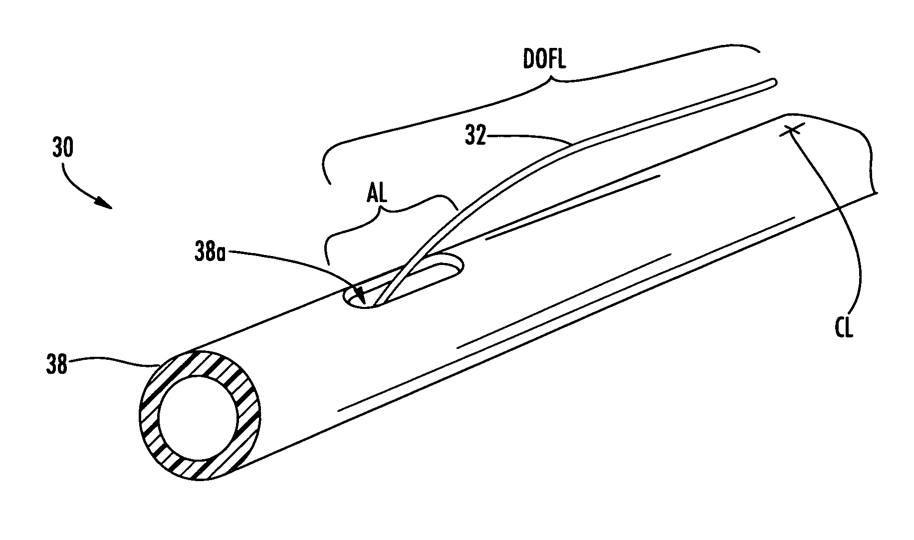
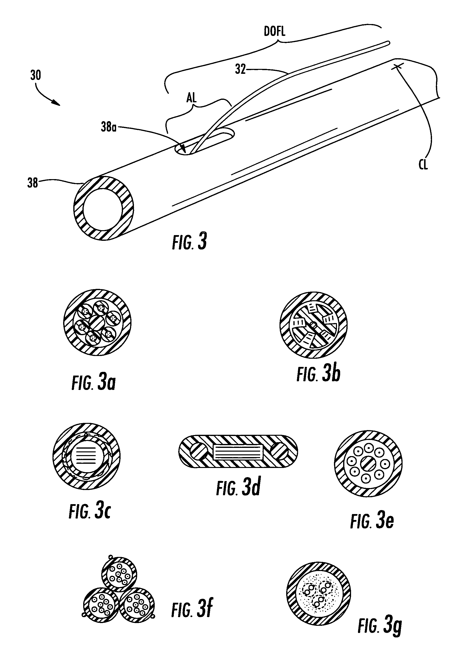
[0040]Reference will now be made in detail to the present preferred embodiments of the invention, examples of which are illustrated in the accompanying drawings. Whenever possible, the same reference numerals will be used throughout the drawings to refer to the same or like parts. The present invention discloses distribution fiber optic cables and methods of making the same where one or more optical fibers of a fiber optic cable are presented outside a protective covering such as a cable jacket for distribution. Additionally, the present invention also discloses tools for the methods of making along with kits of parts useful for making the distribution fiber optic cables. In one embodiment, a relatively small opening is formed at the access location of the fiber optic cable, thereby leaving a relatively small access footprint (i.e., removing a small portion of the protective covering and / or other cable components) on the fiber optic cable. Even though a relatively small opening is m...


PUM


Abstract

Fiber optic distribution cables and methods for manufacturing the same are disclosed. The methods present one or more optical fibers outward of the protective covering for distribution of the same toward the subscriber. In one method of making the fiber optic distribution cables, an indexing tube is provided for indexing a tether tube within the indexing tube for providing the distribution optical fiber with a suitable excess fiber length. In another method, a demarcation point is provided for inhibiting the movement (i.e., pistoning) of the distribution optical fiber into and out of the distribution cable. In still another method, one or more caps are provided for closing one or more the openings in the protective covering used for accessing the optical fibers within the fiber optic distribution cable. Additionally, other methods may include providing a fiber optic distribution cable having a dry construction and / or a non-round cross-section.

Description

RELATED APPLICATIONS[0001]The present application is related to U.S. patent application Ser. No. 11 / 432,637 titled “Tools and Methods for Manufacturing Fiber Optic Distribution Cables”, U.S. patent application Ser. No. 11 / 432,579 titled “Fiber Optic Distribution Cables and Structures Therefor”; and U.S. patent application Ser. No. 11 / 432,654 titled “Kits of Parts for Manufacturing Fiber Optic Distribution Cables” all filed on even date herewith, the disclosures of which are incorporated herein by reference.FIELD OF THE INVENTION[0002]The present invention relates generally to fiber optic distribution cables, methods for manufacturing the same, tools, and kits therefor. More particularly, the present invention relates to fiber optic distribution cables, methods of manufacturing the same, tools, and kits for distributing optical fibers toward subscribers such as in optical fiber to the home or curb applications (FTTx).BACKGROUND OF THE INVENTION[0003]Communication networks are used to...

Claims


Application Information

Patent Timeline
Patent Type & Authority Patents(United States)
IPC IPC(8): G02B6/44
CPCG02B6/4495G02B6/4431
Inventor CODY, JOSEPH T.KNECHT, DENNIS M.LEWALLEN, CHRISTOPHER PAULLUTHER, JAMES P.
Owner CORNING OPTICAL COMM LLC
Why Eureka
Try Eureka