
Workflow system

a workflow and system technology, applied in the field of workflow systems, can solve the problems of stagnant work that method cannot be applied, stagnant work cannot be assigned to another worker,

Inactive Publication Date: 2008-03-18
HITACHI LTD
View PDF13 Cites 29 Cited by
  • Summary
  • Abstract
  • Description
  • Claims
  • Application Information

AI Technical Summary

Benefits of technology

[0006]When a stagnated work occurs, a work relative to the stagnated work is also influenced. For example, in a process instance in which a work existing upstream of a stagnated work is being implemented, the progress of business processing is influenced by the stagnated work. In this case, when a work in a source of movement to be implemented just before the stagnated work has been implemented, the process instance is moved to the stagnated work after completion of the work and the progress of business processing is interrupted in the stagnated work. In such a case, when a worker is engaged in a plurality of different businesses, it is efficient as a whole that the worker implements another business processing preferentially as compared with implementation of the work of which the progress of business is interrupted just after the movement thereto, and human resources of workers can be utilized effectively. Particularly, the degree that the human resources can be utilized effectively is increased when the priority of the work which is moved to the stagnated work after completion of processing thereof is high. This reason is that the worker specifies the work to be processed on the basis of the priority related to the work. In such case, the human resources and the computer resources are preferentially assigned to the work which is moved to the stagnated work regardless of whether a business which can be implemented without stagnation is existent or not, so that its effect is more remarkable.

Problems solved by technology

In the above-mentioned conventional method in which the stagnated work is assigned to another worker to thereby solve the stagnation state, however, when any worker to which the stagnated work is assigned is not existent, the method cannot be applied.
There is a possibility that the stagnated work cannot be assigned to another worker when technical knowledge, a special processing apparatus or the like is required for implementation of the stagnated work or when excess personnel do not exist, for example.
Further, even when the stagnated work can be assigned to another worker, a work is stagnated or delayed if a large quantity of works exceeding the processing ability thereof occur.

Method used


Image

  • Workflow system
  • Workflow system
  • Workflow system

Examples


Embodiment Construction

[0030]A workflow management system according to an embodiment of the present invention is now described. The workflow management system supports management of implementation of works and the progress state of business on the basis of a process definition which previously defines a flow of business composed of a plurality of works, and changes the processing priority in accordance with a stagnation state of work.

[0031]In an example of the workflow management system of the embodiment described below, since functions and details thereof unnecessary for explanation of the present invention are omitted, the system is simplified as compared with a general workflow management system, but an application range of the present invention is not limited.

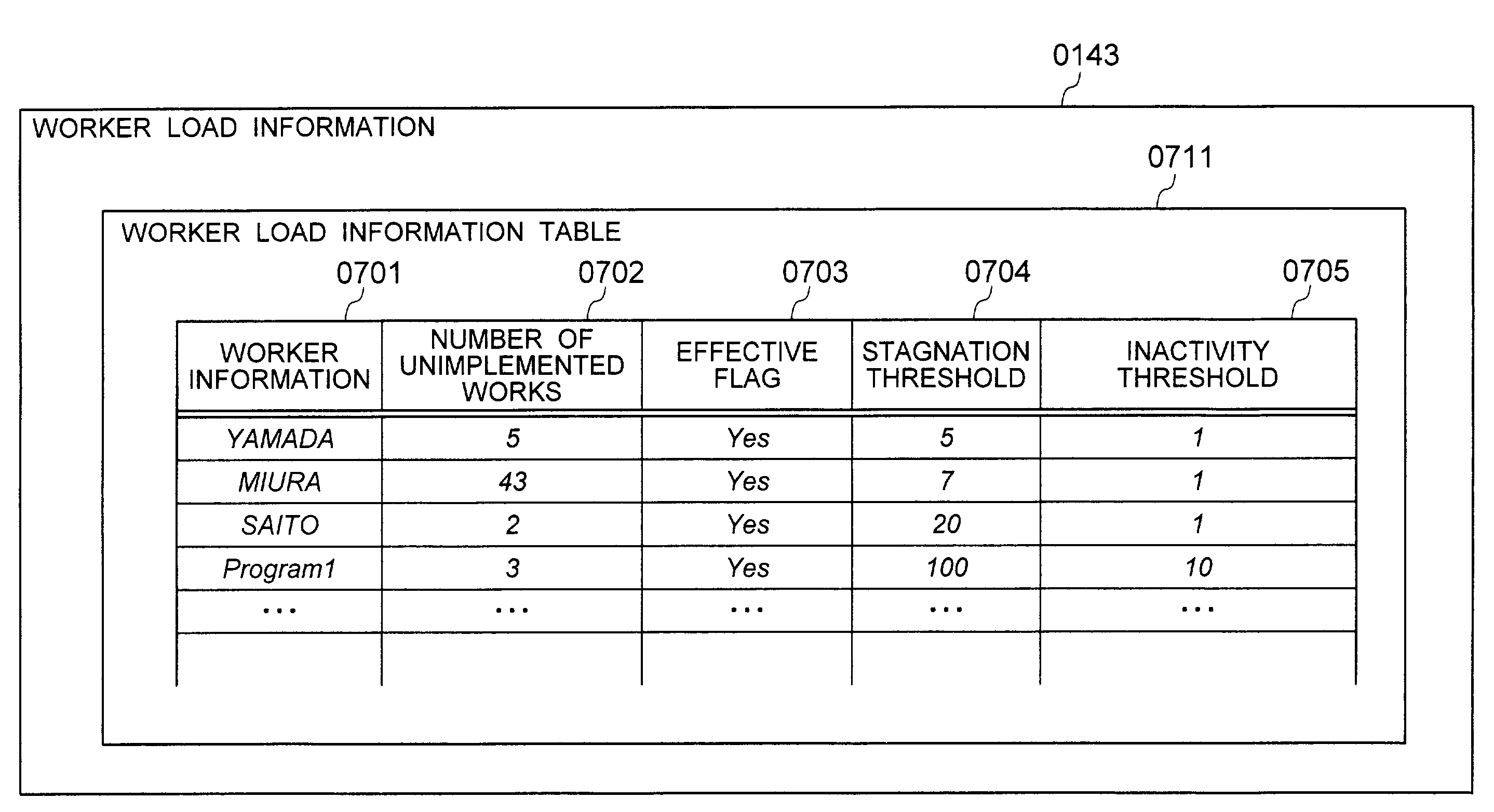
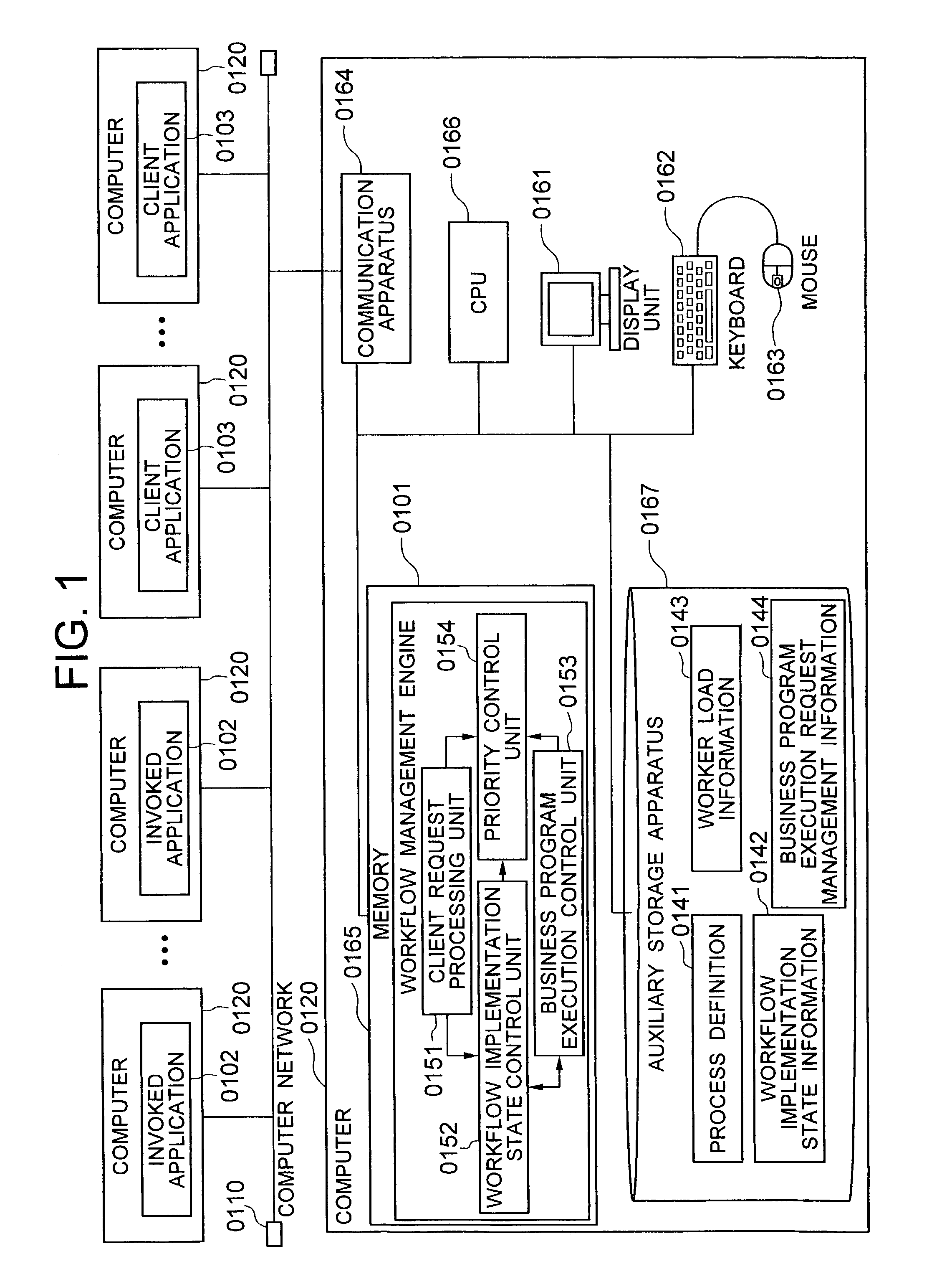
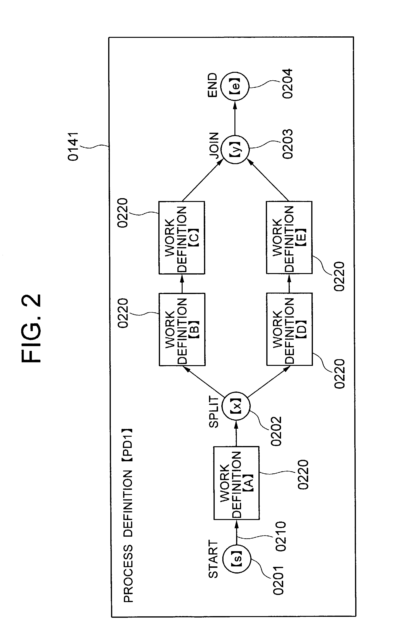
[0032]FIG. 1 is a diagram schematically illustrating the workflow management system of the embodiment. As shown in FIG. 1, a computer 0120 realizing the workflow management system of the embodiment includes a client request processing unit 0151, ...


PUM


Abstract

A workflow system controls work which includes a plurality of works. A stagnated work in a stagnation state is grasped, and processing priorities of works having a relation to the stagnated work are established in accordance with the relation. Particularly, a processing priority of a work, of which the processing progress is influenced due to the stagnated work in the stagnation state, is established to be lower.

Description

BACKGROUND OF THE INVENTION[0001]The present invention relates to a workflow system for supporting management of implementation of works and the progress state of business composed of a plurality of works on the basis of a process definition which previously defines a flow of business, and more particularly to technique effective for application to a workflow system for supporting management of implementation of works and the progress state of business in consideration of the presence of a stagnated or delayed work in the business, in the workflow management system.[0002]The workflow system is the technique for defining a flow of business composed of a plurality of works as a process definition previously and supporting management of implementation of the works and the progress state of the business on the basis of the process definition. The process definition is said to be a modeled flow of business. Processing in each work is sometimes performed by people and is sometimes execute...

Claims


Application Information

Patent Timeline
IPC IPC(8): G06F17/50G06Q10/06G06Q10/10
CPCG06Q10/06G06Q10/063114G06Q10/06316G06Q10/10
Inventor KUSAMA, TAKATOBENIYAMA, NOBUOSUZUKI, ATSUHITO
Owner HITACHI LTD
Learn More