Packet transfer device

a packet transfer and packet technology, applied in the field of packet transfer devices, can solve the problems of inefficient use of server resources, waste of surplus server resources without being utilized by users connected via other network interfaces, and inability to allocate surplus resources to other services, so as to improve service quality

Inactive Publication Date: 2006-05-04
HITACHI LTD
View PDF8 Cites 96 Cited by
  • Summary
  • Abstract
  • Description
  • Claims
  • Application Information

AI Technical Summary

Benefits of technology

[0037] This invention improves service quality to the maximum extent within a server resource range by collecting a surplus resource from every portion of a server

Problems solved by technology

This method of performing uniform or utilization-history-basis bandwidth control on network interfaces that receive request packets from users in order to limit the amount of service requests received by the server within a certain range raises the following problem: when the amount of service requests received from users varies from one network inte

Method used


Image

  • Packet transfer device
  • Packet transfer device
  • Packet transfer device

Examples


Embodiment Construction

[0054] Embodiments of this invention will be described below with reference to the accompanying drawings.

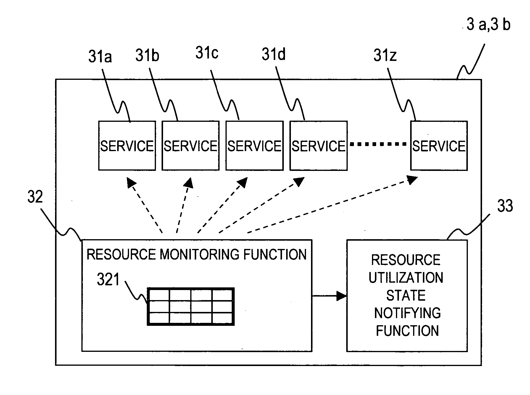
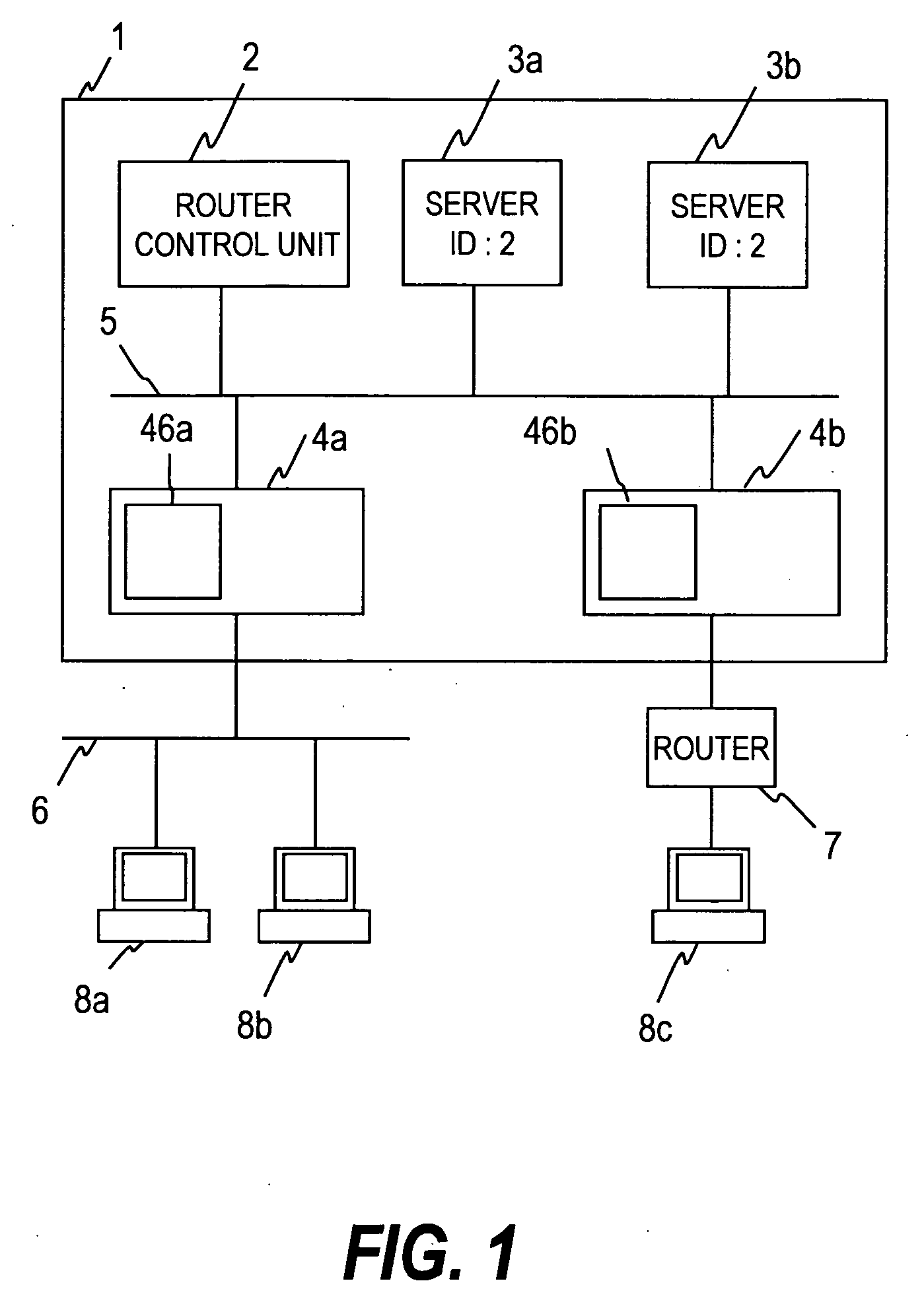
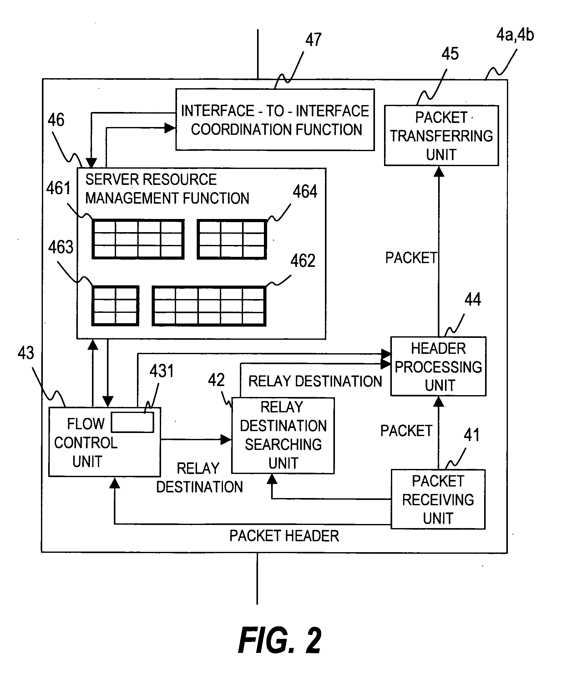
[0055]FIG. 1 is a schematic diagram of a router according to this invention. A router 1 of this invention is composed of a router control unit 2, one or plurality of servers 3a and 3b, and network interfaces 4a and 4b, which are connected to one another by an internal switch interface 5. Each server can provide a plurality of services. Via a switch network 6 or a network constituted of a router 7, the router 1 of this invention receives service requests from a plurality of user terminals 8a to 8c. One of the servers 3a and 3b that is designated by a received service request processes the service request, and responds to a user terminal 8a to 8c that has sent the service request.

[0056] In the router 1 of this invention, a server resource management function of the network interfaces 4a and 4b, which will be described later, manages resource allocation of each service and service...


PUM


Abstract

A router with a server incorporated to provide services has a problem in that the server's resource cannot be allocated dynamically according to user requests. Service request packets received at a plurality of network interfaces are controlled such that the total bandwidth of the service request packets does not exceed a preset threshold. This makes it possible to process as many service requests from users as possible while limiting a server resource occupied by one service to a fixed amount. The network interfaces are notified of how much of a server resource is occupied by each service. In the case where one service consumes less than its allocated resource amount, the resultant surplus resource is made available to other services by easing the bandwidth control on other services. The above problem is thus solved.

Description

CLAIM OF PRIORITY [0001] The present application claims priority from Japanese application P2004-316400 filed on Oct. 29, 2004, the content of which is hereby incorporated by reference into this application. BACKGROUND OF THE INVENTION [0002] This invention relates to a router constituting an IP (Internet Protocol) network. More specifically, the invention relates to a method and device to sort traffic by service type at a node between a server site and an IP network, thereby controlling the flow rate of each stream of traffic and ensuring a response to users for each service type. [0003] A QoS (Quality of Service) function of a router is employed to ensure quality of respective services provided via a network. With the QoS function, packets of individual services are assigned their respective bandwidths on a connection line so that a high priority service can preferentially be delivered to users. [0004] The QoS function is a function for per-flow bandwidth control and per-flow prio...

Claims


Application Information

Patent Timeline
IPC IPC(8): H04J3/22H04L47/525H04L47/76H04L47/80
CPCH04L12/2854
Inventor OKITA, HIDEKISAZUKI, TOSHIAKI
Owner HITACHI LTD
Why Eureka
Try Eureka