Hand-held power tool with angle drive

a technology of angle drive and power tool, which is applied in the direction of portable power-driven tools, metal sawing equipment, toothed gearings, etc., can solve the problem of limited axial displacement of the drive shaft, and achieve the effect of limiting the axial displacement backlash, minimal backlash of 0.05 mm, and high degree of quietness

Inactive Publication Date: 2008-03-25
HILTI AG
View PDF16 Cites 13 Cited by
  • Summary
  • Abstract
  • Description
  • Claims
  • Application Information

AI Technical Summary

Benefits of technology

[0012]According to the invention, the drive and driven toothings so cooperate with each other that with an increased resistive torque being applied to the tool holder, the drive toothing is pressed by the driven toothing in the direction of the driven shaft. However, the resulting axial displacement of the drive shaft is limited by the axial stop on the driven shaft to a predetermined amount. The axial stop can be formed by the driven shaft itself or by a stop element provided thereon. Thereby, a minimal backlash between engaging each others teeth flanks can be ensured. Preferably, the minimal backlash on the outer diameter of the driven toothing should not decrease below 0.05 mm. The minimal backlash can so limit the stresses which are produced between the drive and the driven toothings during the operation of the tool, that no increased wear occurs.
[0019]Furthermore, the drive axis extends advantageously perpendicular to the driven axis. This ensures a uniform positioning of the drive shaft when it contacts the axial stop.

Problems solved by technology

However, the resulting axial displacement of the drive shaft is limited by the axial stop on the driven shaft to a predetermined amount.

Method used


Image

  • Hand-held power tool with angle drive
  • Hand-held power tool with angle drive
  • Hand-held power tool with angle drive

Examples


Embodiment Construction

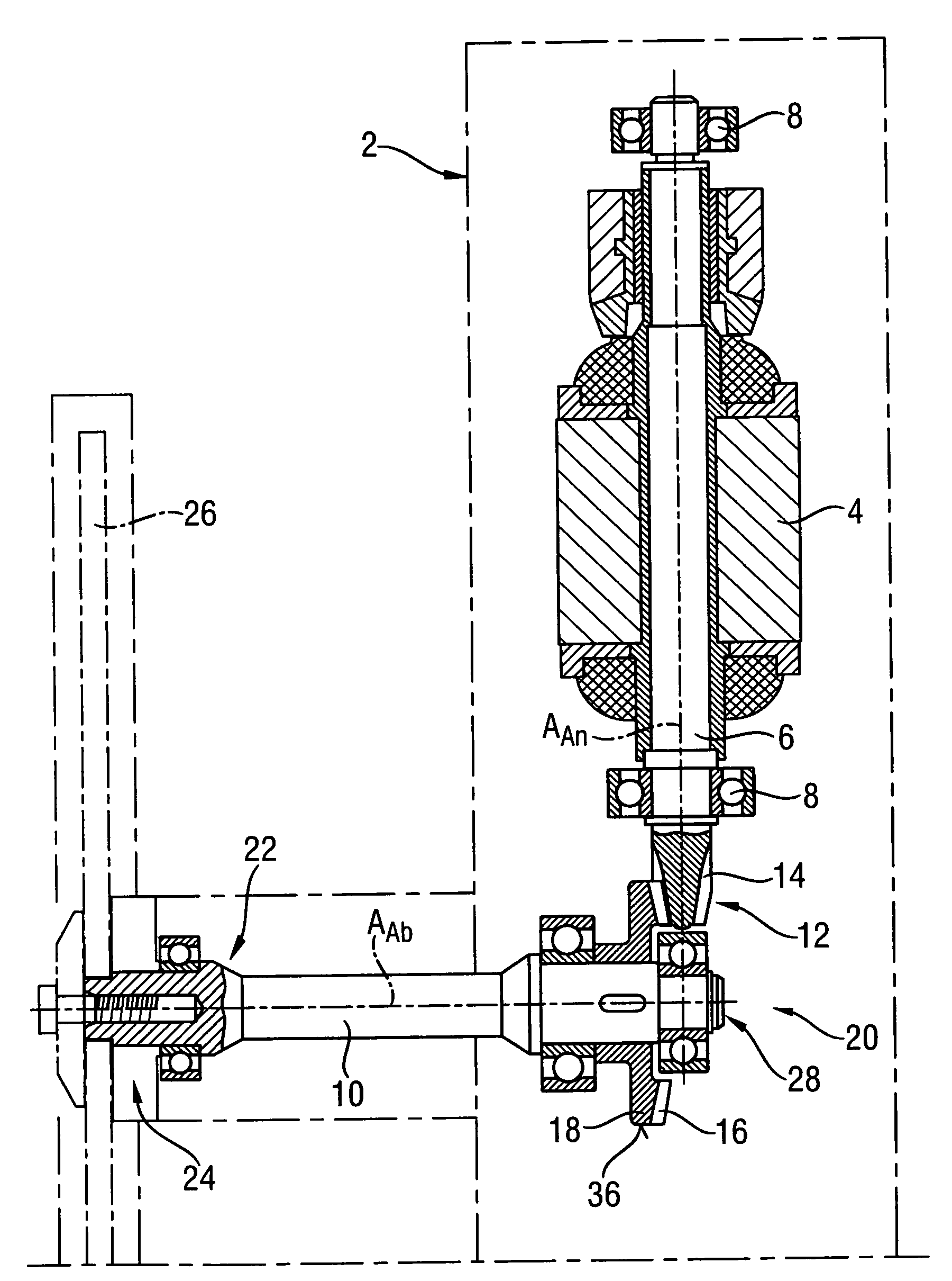
[0025]A hand-held power tool 2 according to the present invention which is shown in FIG. 1, is formed as a circular saw having an electric motor 4 for driving a drive shaft 6. The drive shaft 6 is supported in two roller bearings 8 for rotation about a drive axis AAn.

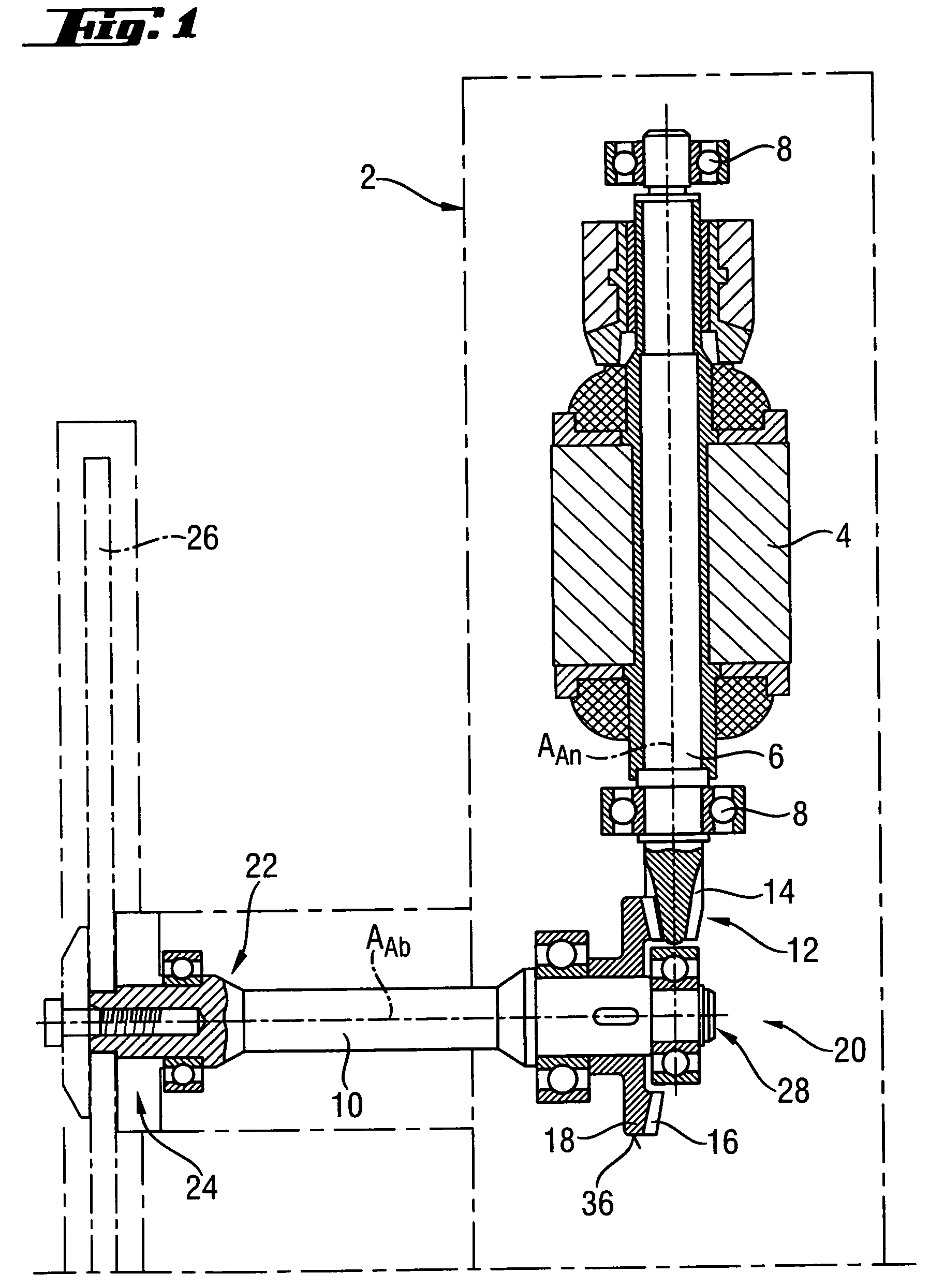
[0026]At its end 12 adjacent to a driven shaft 10, the drive shaft 6 has a drive toothing 14 that cooperates with a driven toothing 16 of the driven shaft 10. The driven toothing 16 is provided on a conical gear 18 which is mounted on the driven shaft 10 with a press fit. Thereby, the driven shaft 10 is driven upon rotation of the drive shaft 6, with the driven shaft 10 being rotatable about the driven axis AAb. The drive axis AAn and the driven axis AAb extend perpendicular to each other, thereby forming an angle drive designated generally with a reference numeral 20.

[0027]As shown in FIG. 1 at an end 22 of the driven shaft 10 remote from the angle drive 20 there is provided a working tool holder 24. On the tool holder...


PUM

PropertyMeasurementUnit
inclination angleaaaaaaaaaa
distanceaaaaaaaaaa

Abstract

A hand-held power tool (2) includes an angle drive (20) for connecting the motor-driven driving shaft (6) and the driven shaft (10) connected with a tooth holder (24) for joint rotation therewith, and having drive toothing (14) provided on the drive shaft (6) and driven toothing (16) provided on the driven shaft and cooperating with the drive toothing (14) for driving the driven shaft (10) in the driven direction (DAb) in response to the drive shaft (6) being driven in the drive direction (DAn), with the driven toothing (16) being inclined over its circumference (36) in a direction opposite the driven direction (DAb), and with the driven shaft (10) having an axial stop (30) for limiting an axial displacement backlash of the drive shaft (6) relative to the driven shaft (10).

Description

BACKGROUND OF THE INVENTION[0001]1. Field of the Invention[0002]The present invention relates to an electrically driven hand-held power tool with an angle drive such as angular grinder, drilling, chiseling, or screw-driving tool, or, in particular, a circular saw.[0003]2. Description of the Prior Art[0004]An angle drive of hand-held power tools of the type described above includes a drive toothing provided on a drive shaft driven by a motor in a preferable drive direction about a drive axis, and a driven toothing provided on a driven shaft which is driven in a preferable driven direction about a driven axis and is connected with a tool holder for the working tool. The driven toothing cooperates with the drive toothing for driving the driven shaft in the preferable drive direction in response to the drive shaft being driven in the preferable drive direction.[0005]The advantage of hand-held tools with angular drives consists in that the drive axis can be arranged at an angle, in parti...

Claims


Application Information

Patent Timeline
Patent Type & Authority Patents(United States)
IPC IPC(8): B27B9/00
CPCB23D47/126B25F5/001F16H1/14Y10T74/19665Y10T74/19698Y10T74/19633
Inventor HUNGER, JOSEF
Owner HILTI AG
Why Eureka
Try Eureka