Control assembly for tufting machine

a technology of control assembly and tufting machine, which is applied in the direction of embroidering machine, instruments, textiles and paper, etc., can solve the problems of limiting the speed of tufting machine operation, gate and clip being particularly vulnerable to wear, fatigue, and malfunction, and tufting process typically needs to be stopped for repair

Active Publication Date: 2008-03-25
CARD MONROE
View PDF73 Cites 57 Cited by
  • Summary
  • Abstract
  • Description
  • Claims
  • Application Information

AI Technical Summary

Problems solved by technology

The reaction time required for the cylinders to actuate and move the gates typically can limit the speed of operation of the tufting machine.
Further, due to the constant actuation / de-actuation of the pneumatic cylinders during the tufting process, the gates and the clips are particularly vulnerable to wear, fatigue, and malfunctions.
As a result, when the apparatus malfunctions, the tufting process typically must be stopped for repair.
For example, the gates and the clip may become uncoupled resulting in malfunctioning of the gate or clip.
If the gate malfunctions, such as by not properly extending, the loop will not be released from the hook, resulting in the production of a flawed tufted product.

Method used


Image

  • Control assembly for tufting machine
  • Control assembly for tufting machine
  • Control assembly for tufting machine

Examples


Embodiment Construction

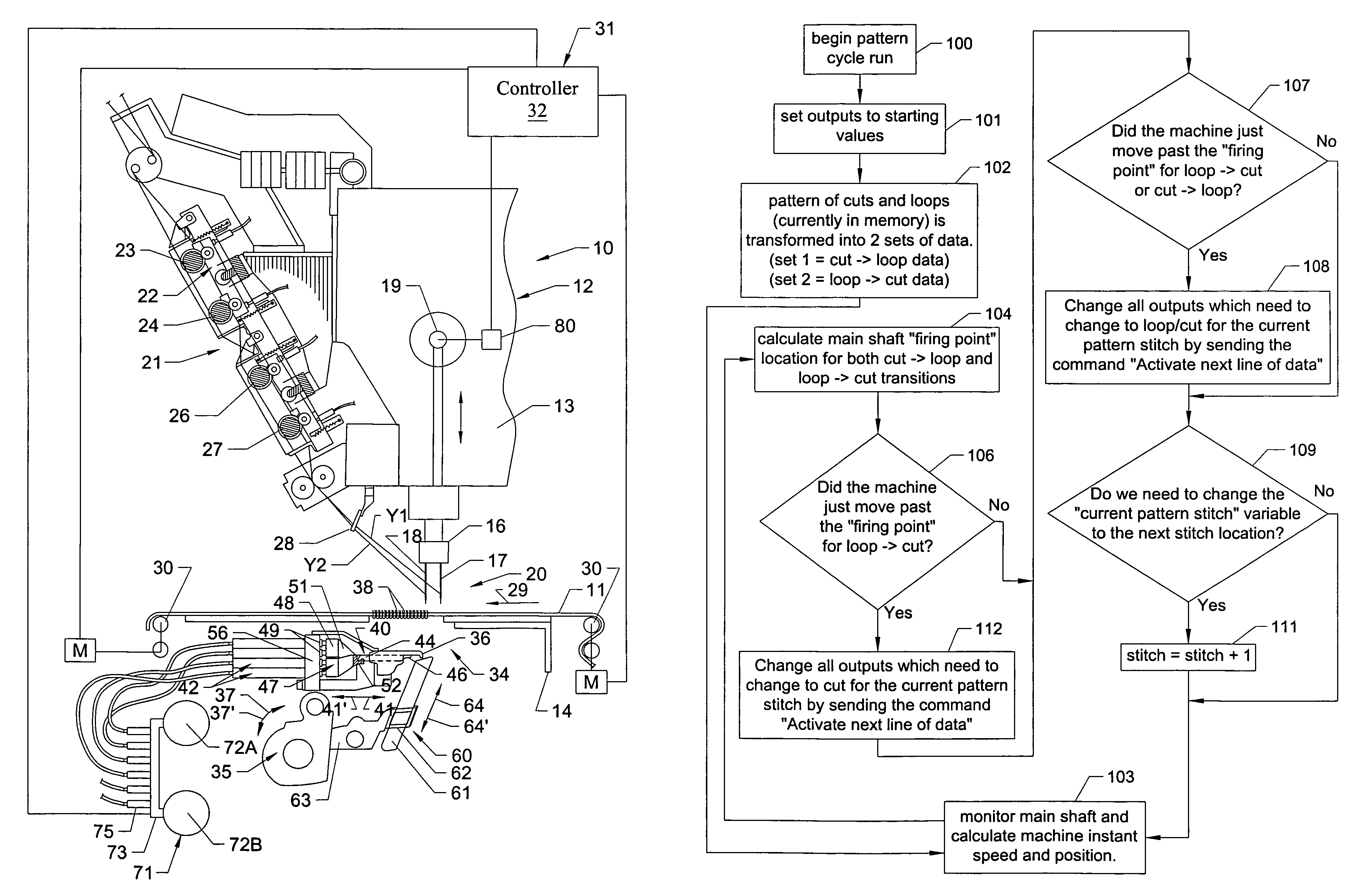
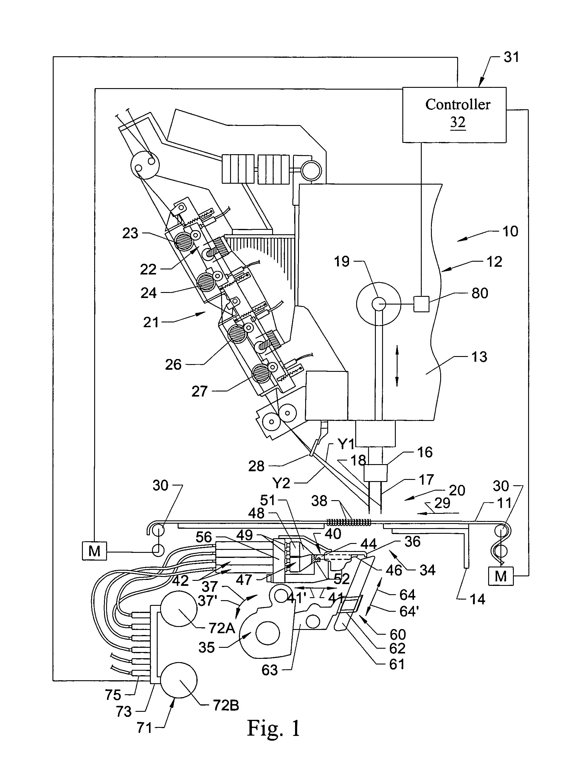
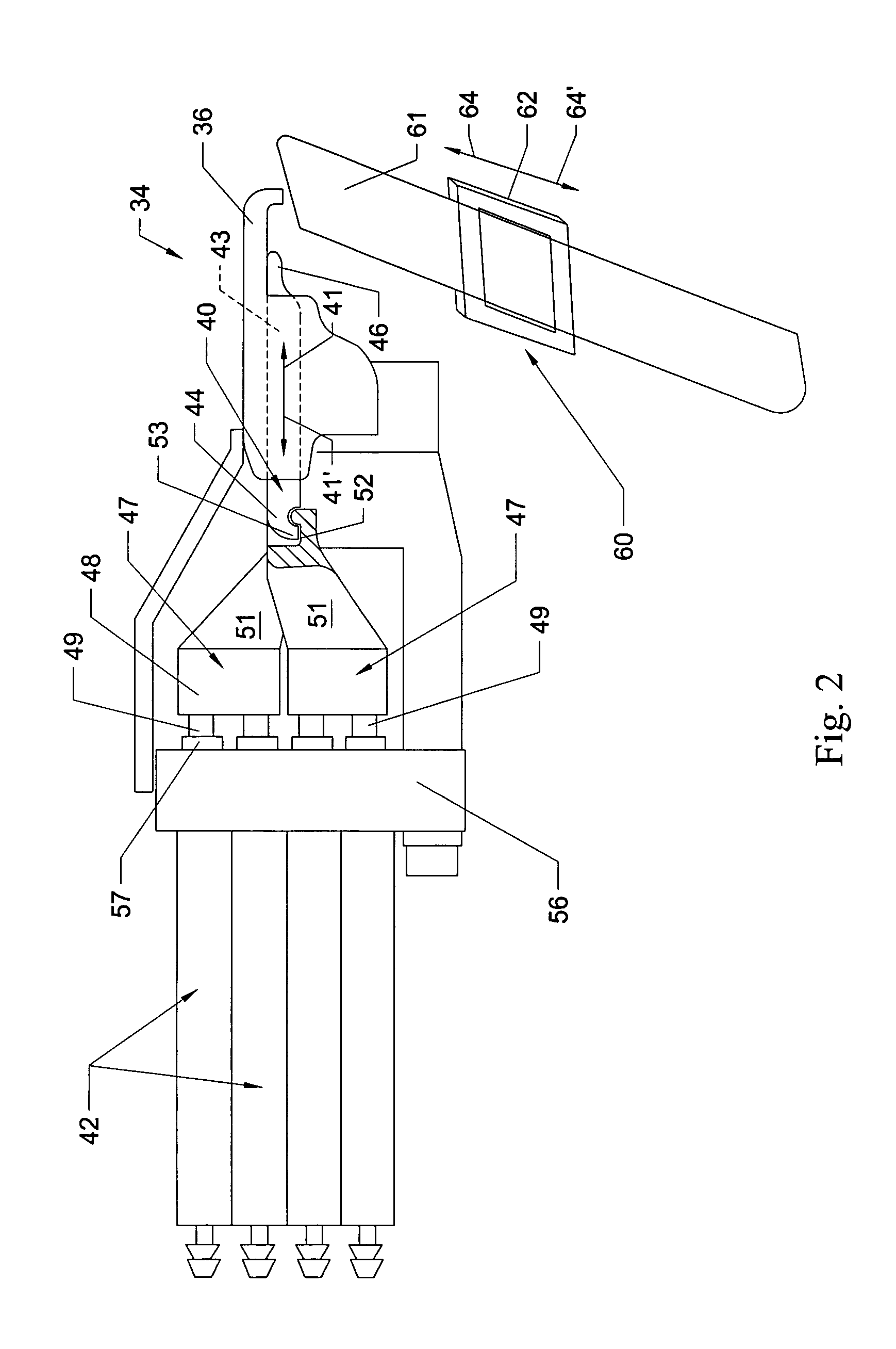
[0024]In accordance with one example embodiment of the present invention, as generally illustrated in FIGS. 1-5B, a tufting machine 10 for forming tufts of yarns in a fabric backing material 11 is provided. As shown in FIG. 1, the tufting machine 10 generally includes a frame 12, having a head or upper portion 13 attached to a base 14; at least one, or a pair of, needle bars 16 carrying spaced rows of needles 17 / 18 and driven off a main shaft 19 of the tufting machine and defining a tufting zone 20; and one or more yarn feed attachments 21. Each yarn feed attachment 21 generally includes a series of yarn feed controls 22 and a series of feed rolls 23, 24, 26 and 27 that feed yarns (shown at Y1 and Y2) through a guide 28, selected ones of the needles 17 and 18. The needle bar 16 further can be shiftable under control of a shift mechanism such as a “Smartstep” shifter as manufactured by Card-Monroe Corp., or other, similar shifter. The backing material 11 is fed through the tufting zo...


PUM


Abstract

A tufting machine and a method of controlling a tufting machine for forming cut and loop pile tufts of yarns in a backing material that includes a hook assembly having a series of hooks / loopers and a series of clips independently moveable between extended and retracted positions. The movement of the clips between their extended and retracted positions is selectively activated to cause transitions from cut pile tufts to loop pile tufts and loop pile tufts to cut pile tufts according to programmed pattern information.

Description

CROSS REFERENCE TO RELATED APPLICATION[0001]The present application claims priority to U.S. Provisional Patent Application Ser. No. 60 / 605,32, filed Aug. 30, 2004.FIELD OF THE INVENTION[0002]The present invention is related to a tufting machine, and more particularly to a tufting machine for forming level cut and loop pile tufts in tufted articles.BACKGROUND OF THE INVENTION[0003]Tufting machines are widely used for manufacturing tufted pile fabrics, such as carpeting. Tufting machines have a plurality of yarn carrying needles. During a tufting operation, the portions of the needles carrying the yarns pass though a heavy fabric backing to form loops of yarn below the fabric. Loopers or hooks that are located below the fabric are oscillated to capture the loops of yarn so that when the needles are withdrawn from the fabric, the loop is held below the fabric to form loop pile tufts. Additionally, the tufting machines can include knives for cutting loops of yarns to form cut pile tufts...

Claims


Application Information

Patent Timeline
Patent Type & Authority Patents(United States)
IPC IPC(8): D05C15/00
CPCD05C15/34
Inventor JOHNSTON, KENDALLCHRISTMAN, JR., WILLIAM M.
Owner CARD MONROE
Why Eureka
Try Eureka