Catheter retention

a catheter and catheter technology, applied in the field of catheter retaining devices, can solve the problems of time-consuming and dangerous, easy breakage during removal, and the downfall of the above-mentioned methods

Inactive Publication Date: 2008-03-25
ANGIODYNAMICS INC
View PDF10 Cites 60 Cited by
  • Summary
  • Abstract
  • Description
  • Claims
  • Application Information

AI Technical Summary

Benefits of technology

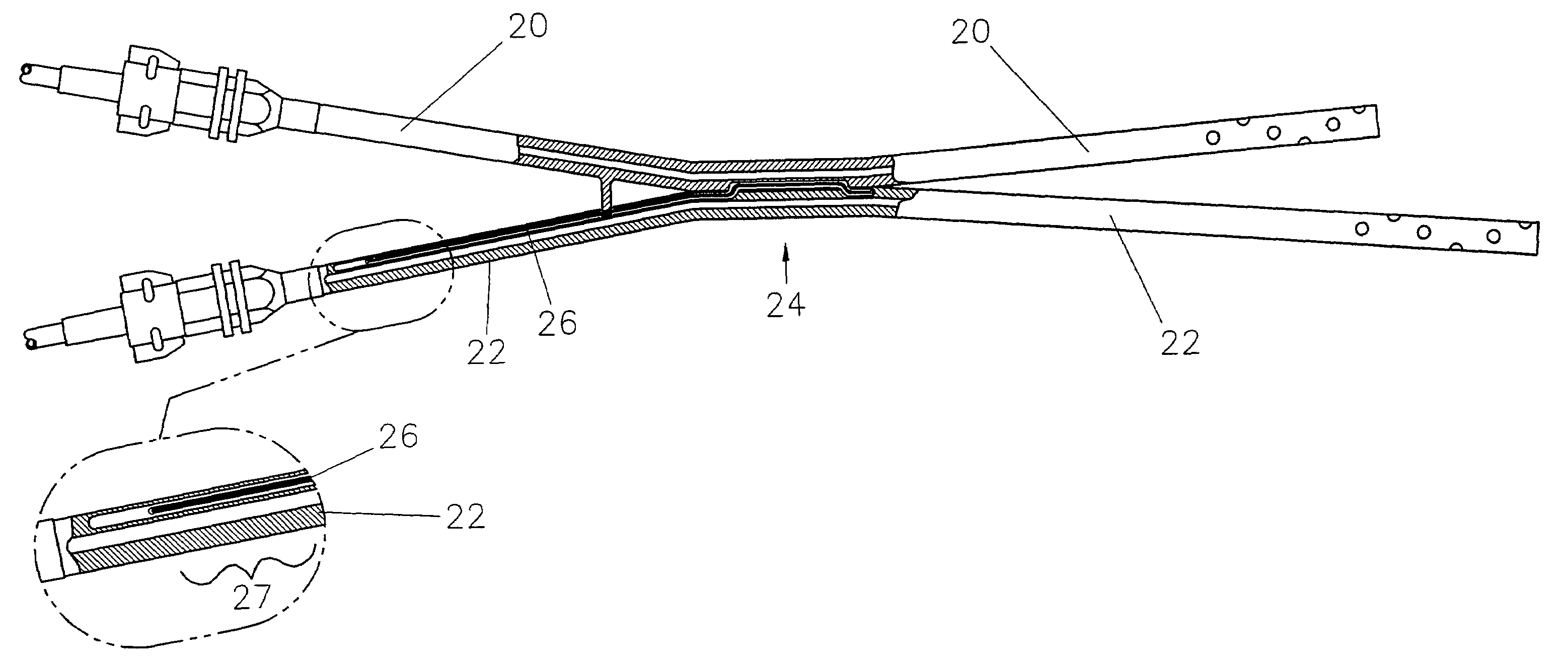
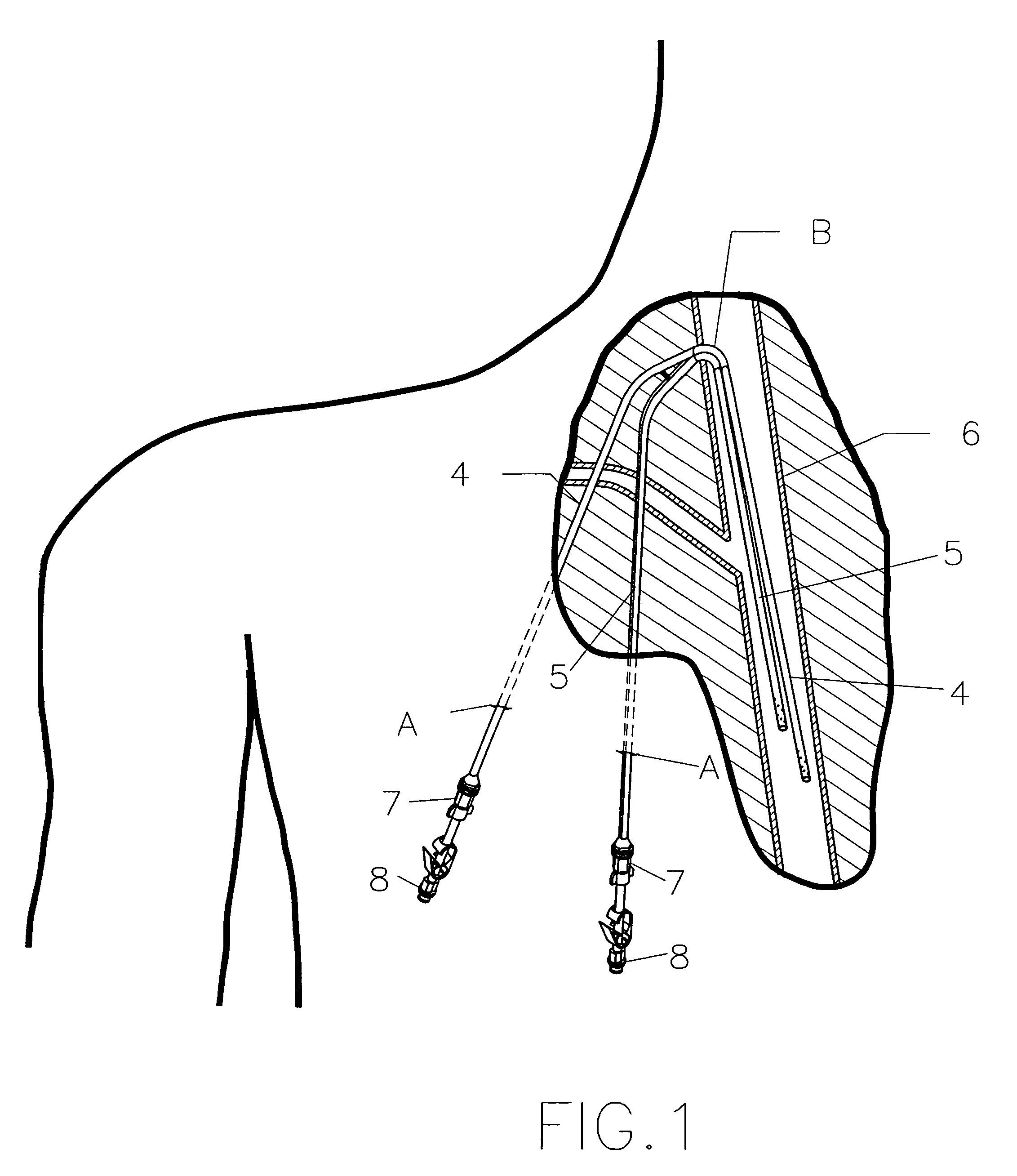
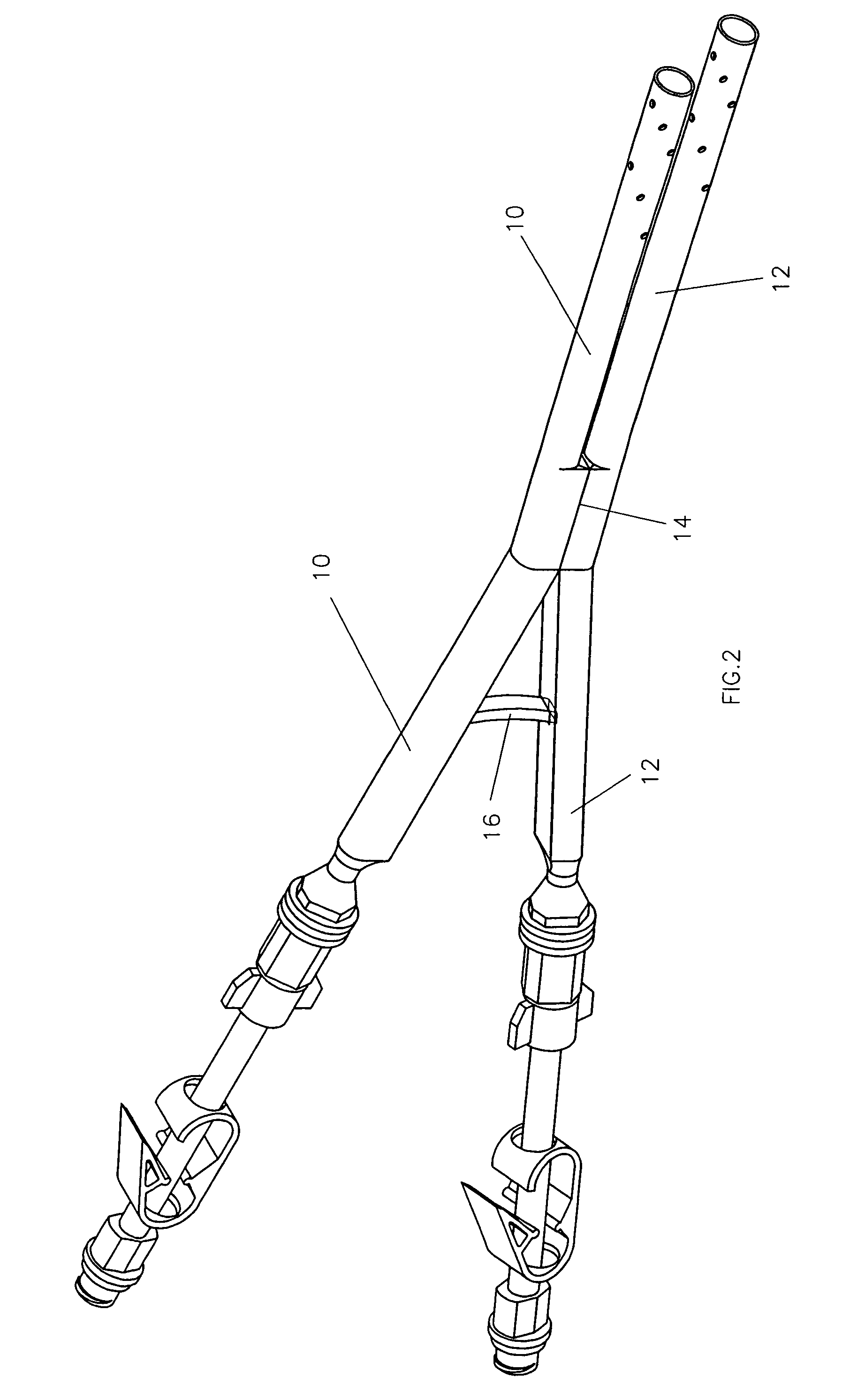
[0005]Accordingly, it is a major object of this invention to provide a multiple tube catheter design, of which a hemo-dialysis catheter is a prominent example, wherein the catheter design provides an enhanced trade-off of effective anchoring in the patient with ease of removal by a doctor.
[0006]It is a related purpose of this invention to provide this ease of removal without requiring surgery to loosen the catheter for the purpose of removing the catheter.
[0007]It is a further related object of this invention to provide this improved multiple tube catheter in a design which readily adapts to currently employed techniques for catheter insertion.
[0008]It is a further related object of this invention to provide the above objects in a fashion that avoids substantial increased costs in product or procedure.
[0009]It is a further related object of this invention to provide the above objects in a device that does not require the cutting or dissection of tissue to remove the catheter and thus reduces the trauma and discomfort to the patient.BRIEF DESCRIPTION

Problems solved by technology

When it is desired to remove these catheters, which may be after a period of two years in place, both of the above discussed methods have their downfalls.
This is time consuming and dangerous.
If the catheter is inadvertently cut, it can easily break during removal.

Method used


Image

  • Catheter retention
  • Catheter retention
  • Catheter retention

Examples


second embodiment

[0044]FIG. 5 illustrates the invention in which the two tubes 30, 32 are adjacent to one another along a zone 34 that provides a dove tail engagement between the two tubes. In this embodiment, the joining wires 36 extends through the teeth of both crenellated sections of the dove tail joint 34. The relatively thin flexible prong 38 extends from the wall of the tube 30 and has an end which fits into a recess in the wall of the tube 32. As in other embodiments, the joining wires 36 extend through openings in the end of the prong 38. The removal of the wires 36 and the separation of the tubes 30 and 32 is the same as in the embodiment of FIGS. 3 and 4.

[0045]The FIG. 6 embodiment is similar to the other embodiments in that there are two tubes 40, 42 having flat surfaces adjacent to one another along a zone 44 and having a separating prong 48. The key distinction in FIG. 6 is that the adjacent surface 44 is a longitudinal lap joint and there is only a single joining wire 46. The wire 46 ...

sixth embodiment

[0048]FIG. 9 illustrates a sixth embodiment in which first and second tubes 70, 72 are deployed adjacent to one another along flat faces 74. A first wire 76, called herein a loop wire, is contained in the wall of the tube 72. A second wire 78, called herein an anchor wire is contained in the wall of the other tube 70.

[0049]As may best be seen in FIG. 10, when the catheter is in use, the anchor wire 78 extends through two loops 82 which in turn are soldered to the loop wire 76. This connection holds the two tubes 70, 72 together because the wires 76, 78 are contained within the sidewalls of the tubes 70, 72.

[0050]When it is desired to remove the tubes from the patient, the two tubes are separated to facilitate such removal. The anchor wire 78, as illustrated in FIG. 11, is accessed by a medical professional and withdrawn from the tube 70. This disconnects the anchor wire 78 from the loops 82 and the two tubes 70, 72 can be separated and handled individually.

[0051]It might be noted, t...


PUM


Abstract

A multiple tube catheter, such as a hemo-dialysis catheter, has first and second tubes which are attached to each other over a zone by one or more longitudinally extending wires which joins the two tubes over that zone. When a catheter is implanted in the patient, the attached zone is within the patient so that the catheter cannot be removed or advanced. When the catheter is to be removed, the longitudinally extending wire or wires are pulled proximally out of the tubes involved so that the two tubes can be separated and individually removed. A flexible separating prong within the patient and proximal of the zone holds the tubes apart to further assure that the catheter cannot be moved.

Description

BACKGROUND OF THE INVENTION[0001]This invention relates in general to a device and method for retaining a catheter in a patient and more particularly to the retention of a dual tube hemo-dialysis catheter.DESCRIPTION OF PRIOR ART[0002]Dual tube hemo-dialysis catheters are used to provide long term access to the venous system. The catheter contains two lumens. One lumen for withdrawal, and one lumen for return blood flow. Hemo-dialysis filtration machines are connected to the catheter at regular intervals such as every other day. The patient's blood is removed, filtered, and returned to the patient. A catheter of this design is described by Ash et al. in U.S. Pat. No. 5,947,953. These catheters must be fixed to the patient to prevent the catheter from pulling out or advancing into the patient. The most common method is to tunnel the catheter from the point of venous access towards a remote location where the catheter is brought out of the skin. This tunnel may be from 5-20 cm long. A...

Claims


Application Information

Patent Timeline
Patent Type & Authority Patents(United States)
IPC IPC(8): A61M25/00A61M1/36
CPCA61M1/3653A61M1/3661A61M2025/0031A61M2025/0034A61M2025/0037A61M1/3659
Inventor HOBBS, EAMONN P.APPLING, WILLIAM M.TARRICONE, ANGELO J.BEYER, THEODORE J.
Owner ANGIODYNAMICS INC
Why Eureka
Try Eureka