
Power tool with internal fastening element

a technology of fastening element and power tool, which is applied in the direction of insulated conductors, electrical apparatus casings/cabinets/drawers, coupling device connections, etc., can solve the problems of inability to accurately position or fix, the fixation of internal components of the power tool is also relatively complicated, and the production cost can be reduced. , the effect of cost advantages

Inactive Publication Date: 2008-03-25
ROBERT BOSCH GMBH
View PDF8 Cites 0 Cited by
  • Summary
  • Abstract
  • Description
  • Claims
  • Application Information

AI Technical Summary

Benefits of technology

The solution provides secure component fixation, reduces production costs, enhances design flexibility, and simplifies assembly and maintenance, while minimizing weight and improving safety and recyclability.

Problems solved by technology

The result can be imprecise positioning or fixation.
Assembly is also relatively complicated, since the components are first placed loosely in one housing half and then fixed only when the second housing half is fastened to the first housing half.
Moreover, this kind of fixation of the internal components of the power tool has disadvantages if the power tool is dropped, since if there is damage to the housing, the fixation of the internal components can also easily be damaged.
In the case of single fixation of the internal components on the housing, however, many different fixation points result, making assembly very expensive.
Moreover, this has design limitations for the housing, since many fastening domes must be provided on the housing, so that the individual components can be accurately positioned by and fastened to them.
The use of complex composite components further has the disadvantage that the production of such components is very expensive.
Moreover, this has disadvantages in servicing, particularly since the entire composite component must always be replaced even if only a small part of the composite component is damaged.
Moreover, recycling such composite components is relatively complicated and expensive.

Method used


Image

  • Power tool with internal fastening element
  • Power tool with internal fastening element
  • Power tool with internal fastening element

Examples


Embodiment Construction

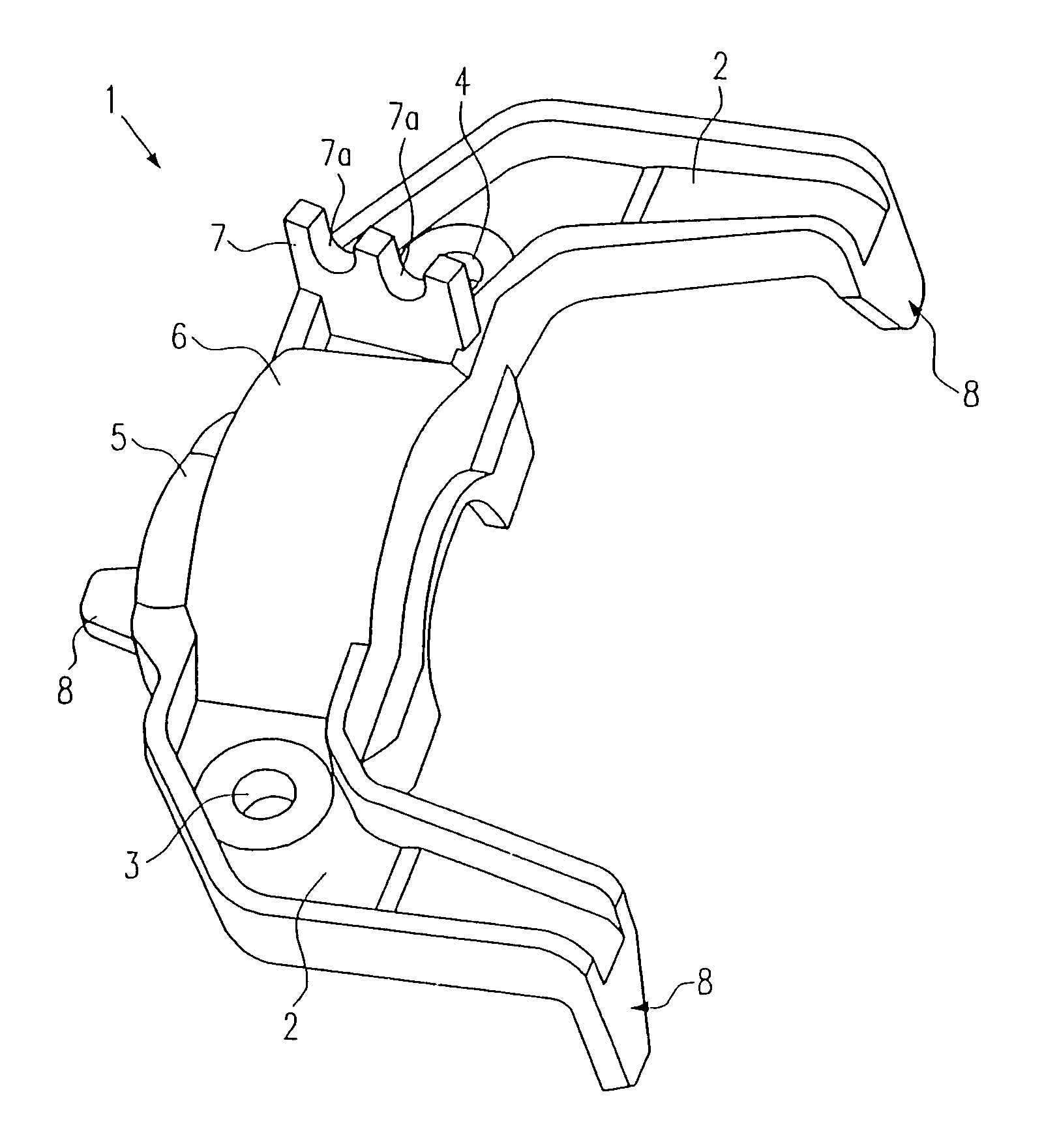
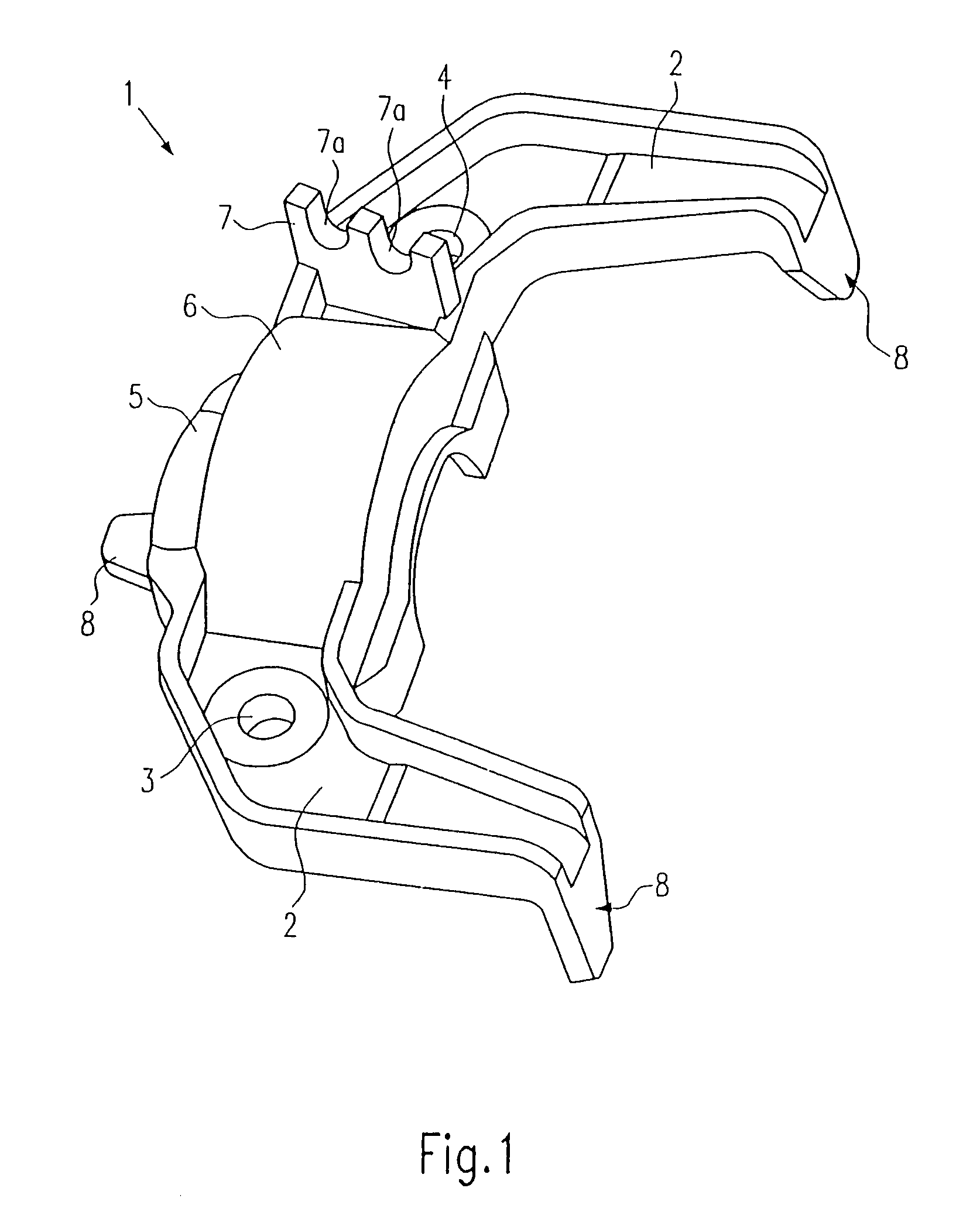
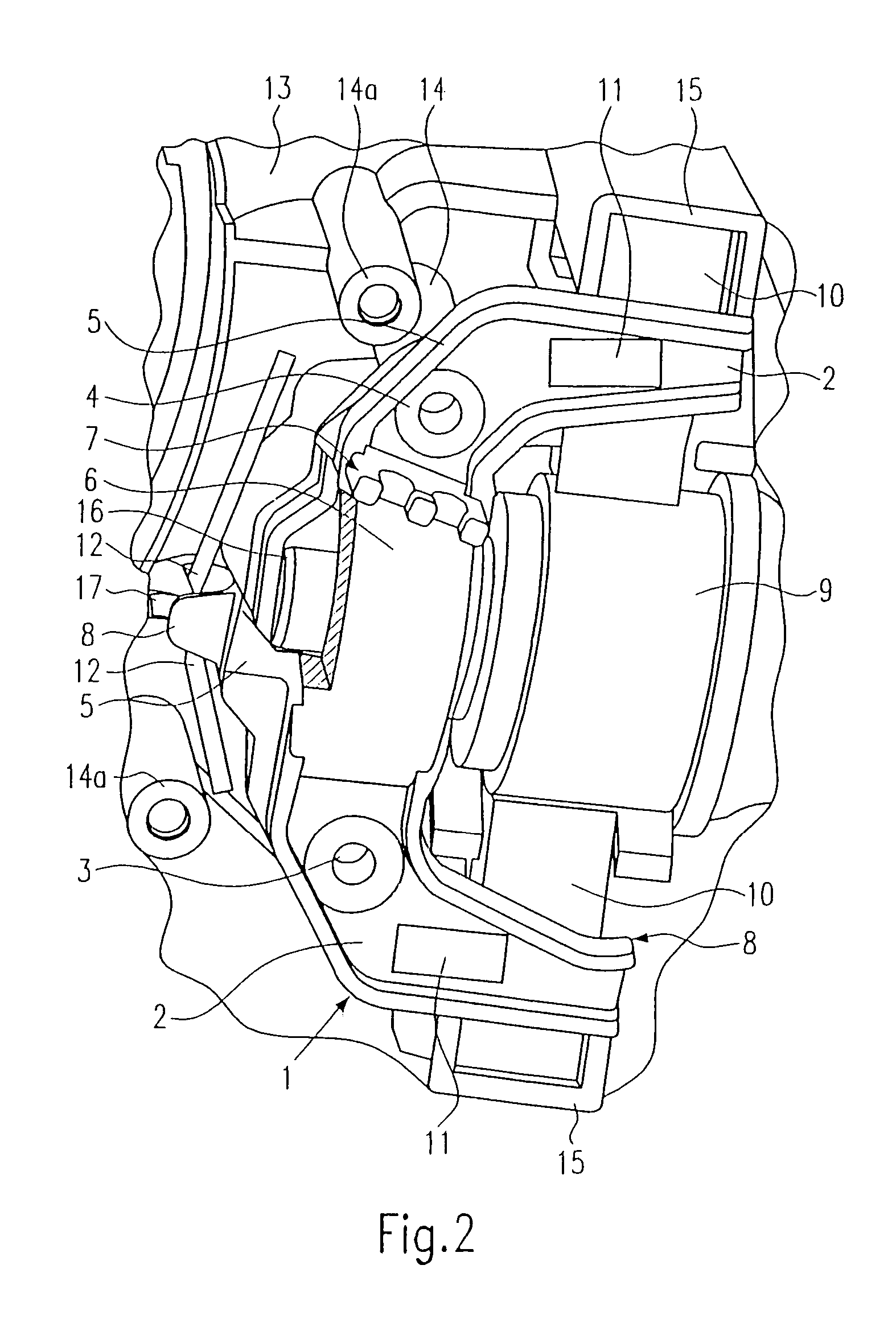
[0017]As can be seen from FIG. 1, the fastening element 1 according to the invention is constructed in the manner of a bridge and has a common air and cable guide conduit 2 on both sides. Two bores 3, 4 are provided in the fastening element 1, by means of which the fastening element 1 can be fastened releasably to a first housing part 13 (see FIG. 2) by means of screws. The bores 3, 4 are provided in the region of the air and cable ducts.

[0018]A dust guard 5 for an armature bearing and a middle covering region 6 are provided in a middle region of the fastening element 1. The covering region 6 is curved and in particular covers an armature shaft 16 (see also FIG. 2). A cable fixation 7 is also provided on the fastening element 1 and has recesses 7a, for positioning cables on the fastening element 1. The recesses 7a are substantially U-shaped and are covered by an inner region of a second housing part in the process of mounting of the second housing part onto the first housing part, s...


PUM


Abstract

The present invention relates to a power tool, including at least a first and a second housing part, many components, in particular electric motor components or electrical components, and one fastening element for fastening the many components to the first housing part in such a way that the components are fixed between an inside of the first housing part and the fastening element.

Description

CROSS-REFERENCE TO RELATED APPLICATIONS[0001]This application is based on German Patent Application 10 2004 036 805.8 filed Jul. 29, 2004, upon which priority is claimed.BACKGROUND OF THE INVENTION[0002]1. Field of the Invention[0003]The present invention relates to a power tool having an additional fastening element which is located in the interior of the power tool.[0004]2. Description of the Prior Art[0005]Power tools in various forms are known from the prior art. Typically, power tools have two housing halves, which surround many components of the power tool. The components are usually electrical or electromechanical components of the electric motor, and these components are clamped between the two housing halves. The result can be imprecise positioning or fixation. Assembly is also relatively complicated, since the components are first placed loosely in one housing half and then fixed only when the second housing half is fastened to the first housing half. Moreover, this kind o...

Claims


Application Information

Patent Timeline
Patent Type & Authority Patents(United States)
IPC IPC(8): H02G3/08H02K5/14H02K5/16H02K5/22
CPCH02K5/148H02K5/161H02K5/225B25F5/02
Inventor DUESSELBERG, ACHIMULLRICH, ANDRESIEBER, KURT
Owner ROBERT BOSCH GMBH
Learn More