
Motion control using electromagnetic forces

a technology of electromagnetic force and motion control, applied in the direction of electromagnets, dynamo-electric machines, synchronous motor starters, etc., can solve the problems of ineffective simple resistive motor speed control techniques, friction brakes are prone to stick-slip, and the voltage is too low for cost-effective electronic control of motion, etc., to achieve the effect of reducing the variation of speed

Active Publication Date: 2008-03-25
SRINIVASA GORUR NARAYANA
View PDF23 Cites 16 Cited by
  • Summary
  • Abstract
  • Description
  • Claims
  • Application Information

AI Technical Summary

Benefits of technology

[0011]One objective of certain embodiments of the present invention is to extend the domain of electric motor speed control (and general motion control—possibly unpowered or utilizing other prime movers), traditionally characterized by electronic techniques, to small apparatus, like bubble vibration toys, paper dispensers, well pulleys, toothbrushes, display turntables, rotating lollipops, (very-low-cost) timing cams, toy racing cars, drawers, hinged objects, etc. These apparatus will be hereafter collectively referred to as small apparatus (SAs). These apparatus are either unpowered (e.g., human powered) or typically but not exclusively run on one or two AA / AAA batteries, generating, e.g., a maximum of 3V initially, and less after a little use. This voltage is too low for cost-effective electronic control of motion. Indeed, at these voltages (e.g., 1.5V), even simple resistive motor speed control techniques can become ineffective. One object of certain embodiments of the present invention is to achieve such control, possibly in a user-customizable fashion, at low cost. While the invention is primarily targeted at low-cost mass-market applications, this does not limit its use in other contexts, e.g., in high-reliability environments due to simplicity of design, very high-performance apparatus due to easy modification of apparatus static and dynamic behavior to simplify control, design simplification of existing apparatus, etc.
[0023]The amount of control exerted on the apparatus by the three techniques can be constant with time, periodically varying, or aperiodically varying, as desired by the user, and possibly changeable at the time of usage of the apparatus. The invention can be used in conjunction with all existing methods of motion control also. The invention is excellently suited for applications wherein low cost is primary, as it is, in a major embodiment primarily but not exclusively, a passive method, and does not require expensive powered microprocessor+servo / similar devices.
[0036]In at least one embodiment, the at least one prime mover is adapted to cause multiple contiguous cycles of motion having a substantially constant steady-state period of motion for each cycle of motion, during which a profile of the speed of motion within each cycle of motion repeats from cycle to cycle. The profile of the speed of motion may involve the speed of the second component increasing and decreasing with respect to the first component within each cycle. Electromagnetic interaction between the first and second components may reduce variations of speed within the profile of the speed of motion otherwise caused by the prime mover.

Problems solved by technology

This voltage is too low for cost-effective electronic control of motion.
Indeed, at these voltages (e.g., 1.5V), even simple resistive motor speed control techniques can become ineffective.
The primary reason being that these embodiments of load control are dissipative methods, and friction brakes are prone to stick-slip.

Method used


Image

  • Motion control using electromagnetic forces
  • Motion control using electromagnetic forces
  • Motion control using electromagnetic forces

Examples


Embodiment Construction

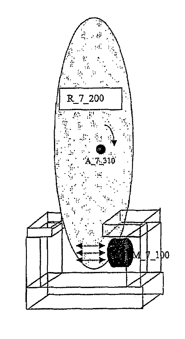
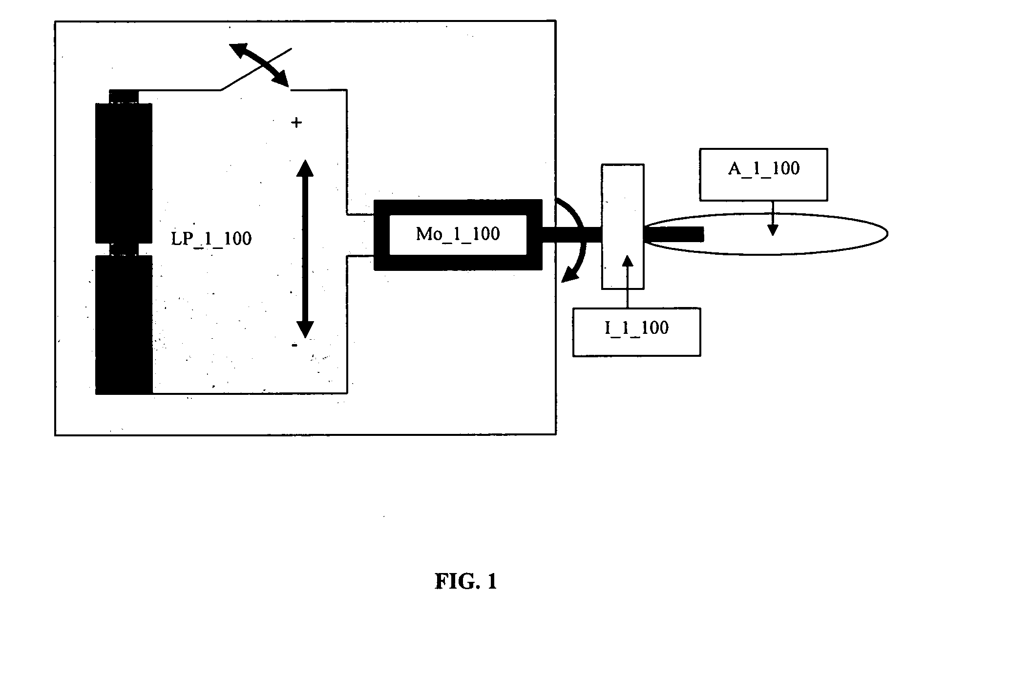
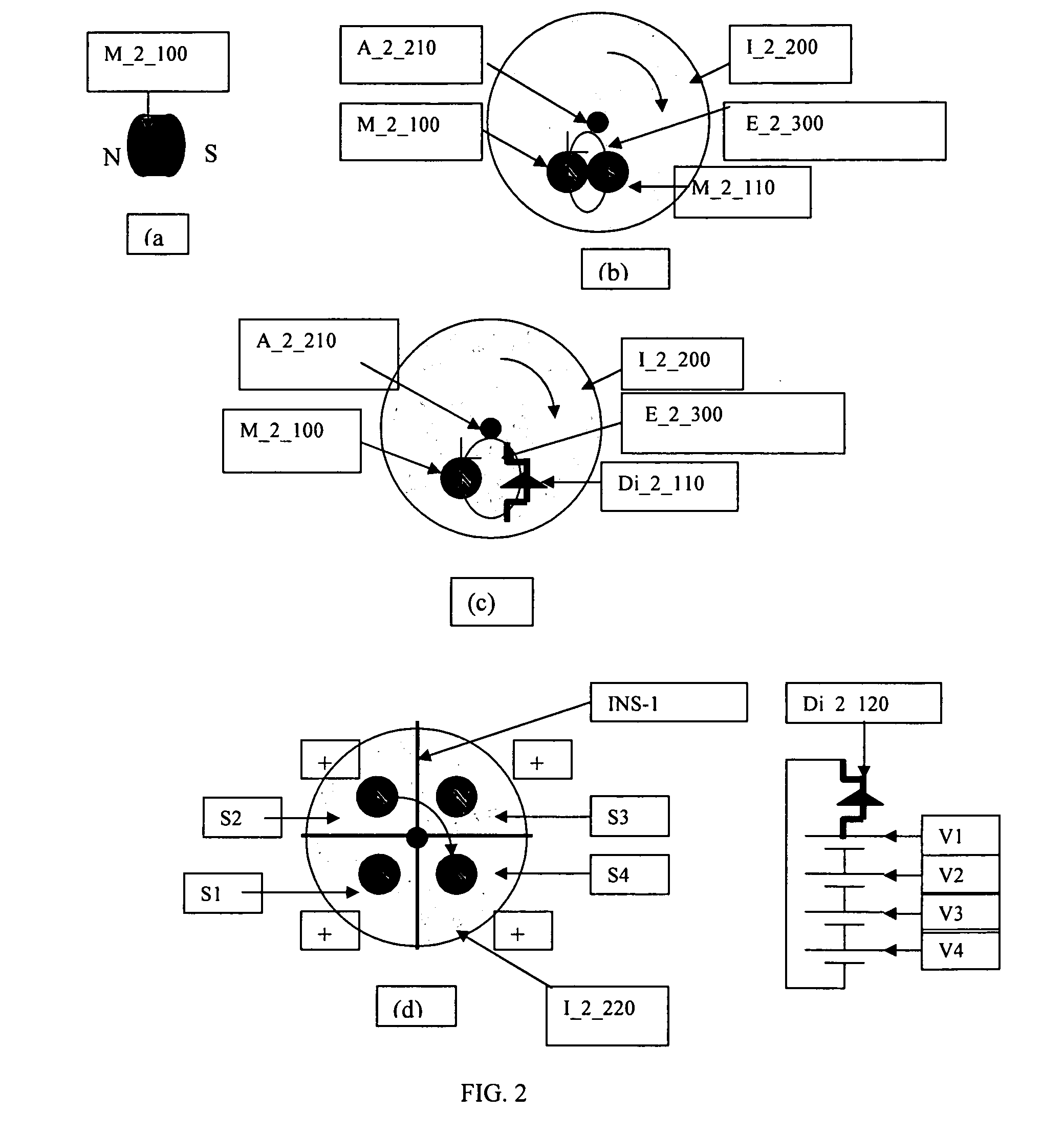
[0115]The present invention extends the domain of electric motor speed control (and general motion control using possibly other prime movers or unpowered motion), traditionally characterized by electronic techniques, to small apparatus (SAs). Primarily but not exclusively, physical motion of appropriately shaped, magnetic flux-producing devices, and appropriately shaped, interacting devices (primarily but not exclusively magnets and / or conductive and / or ferromagnetic portions of the apparatus) is used for the control. In particular, we describe modifications of electric motors, induction clutches and brakes, and electromagnetic actuators, yielding new devices, which can be used for controlling motion of a large variety of apparatus.

[0116]Our techniques offer the ability to perform detailed control of motion timing in mechanisms, and arbitrary timing functions can be generated. We also describe new application of our devices in existing apparatus, as well as new kinds of apparatus, y...


PUM


Abstract

An apparatus has (a) a first component having one or more electromagnetic elements and (b) a second component having one or more electromagnetic elements and movably coupled to the first component. The second component moves with respect to the first component in a cyclical manner. The one or more electromagnetic elements of the first component interacts with the one or more electromagnetic elements of the second component during each of one or more cycles of motion of the second component with respect to the first component such that, when a constant force profile is applied to move the second component with respect to the first component, the speed of motion increases and decreases one or more times during each cycle of motion due to different levels of electromagnetic interaction between the electromagnetic elements within each cycle of motion.

Description

CROSS-REFERENCE TO RELATED APPLICATIONS[0001]This application is a National Stage application of International Application No. PCT / US2004 / 010236, filed Apr. 2, 2004, which claims the benefit of the filing date of U.S. provisional application No. 60 / 461,883, filed on Apr. 10, 2003, the teachings of which are incorporated herein by reference.BACKGROUND OF THE INVENTION[0002]1. Field of the Invention[0003]This invention pertains to the use of electromagnetic force / torque for control of motion in unpowered apparatus and apparatus driven by electric motors and / or other prime movers.[0004]2. Description of the Related Art[0005]Power control (PC) refers to control over the power generated at one or more input to an electromechanical apparatus. Prior-art power control mainly deals with relatively large apparatus. U.S. Pat. No. 6,380,709 (Nishimura et al.) teaches an improved means of driving a motor, using controlled switching of power transistors, to obtain better rotation characteristics....

Claims


Application Information

Patent Timeline
Patent Type & Authority Patents(United States)
IPC IPC(8): H02P25/08H02K41/02H02K49/04H02K49/06H02K49/10
CPCH02K49/046H02K49/065H02K49/10H01F7/06H02P31/00A63H33/28H01F7/0205H02K2201/18
Inventor PRASANNA, GORUR NARAYANA SRINIVASA
Owner SRINIVASA GORUR NARAYANA
Learn More