Electric vacuum cleaner

Inactive Publication Date: 2008-04-01
SANYO ELECTRIC CO LTD
View PDF13 Cites 29 Cited by
  • Summary
  • Abstract
  • Description
  • Claims
  • Application Information

AI Technical Summary

Benefits of technology

[0005]The present invention has been made for solving such a problem, and it is an object thereof to provide an upright type electric vacuum cleaner which can perform both floor cleaning and handy cleaning using an

Problems solved by technology

However, it is the case with such a vacuum cleaner having two flow paths that, owing to the fact that the suction efficiency is apt to be degraded, a flow path switching mechanism for selectively closing one flow path which is not in use needs to be provided, which results in a complicated overall structure.
For instance, the electric vacuum cleaner as disclosed in the above refe

Method used


Image

  • Electric vacuum cleaner
  • Electric vacuum cleaner
  • Electric vacuum cleaner

Examples


Embodiment Construction

[0023]The electric vacuum cleaner of the present invention will now be explained in details with reference to the drawings.

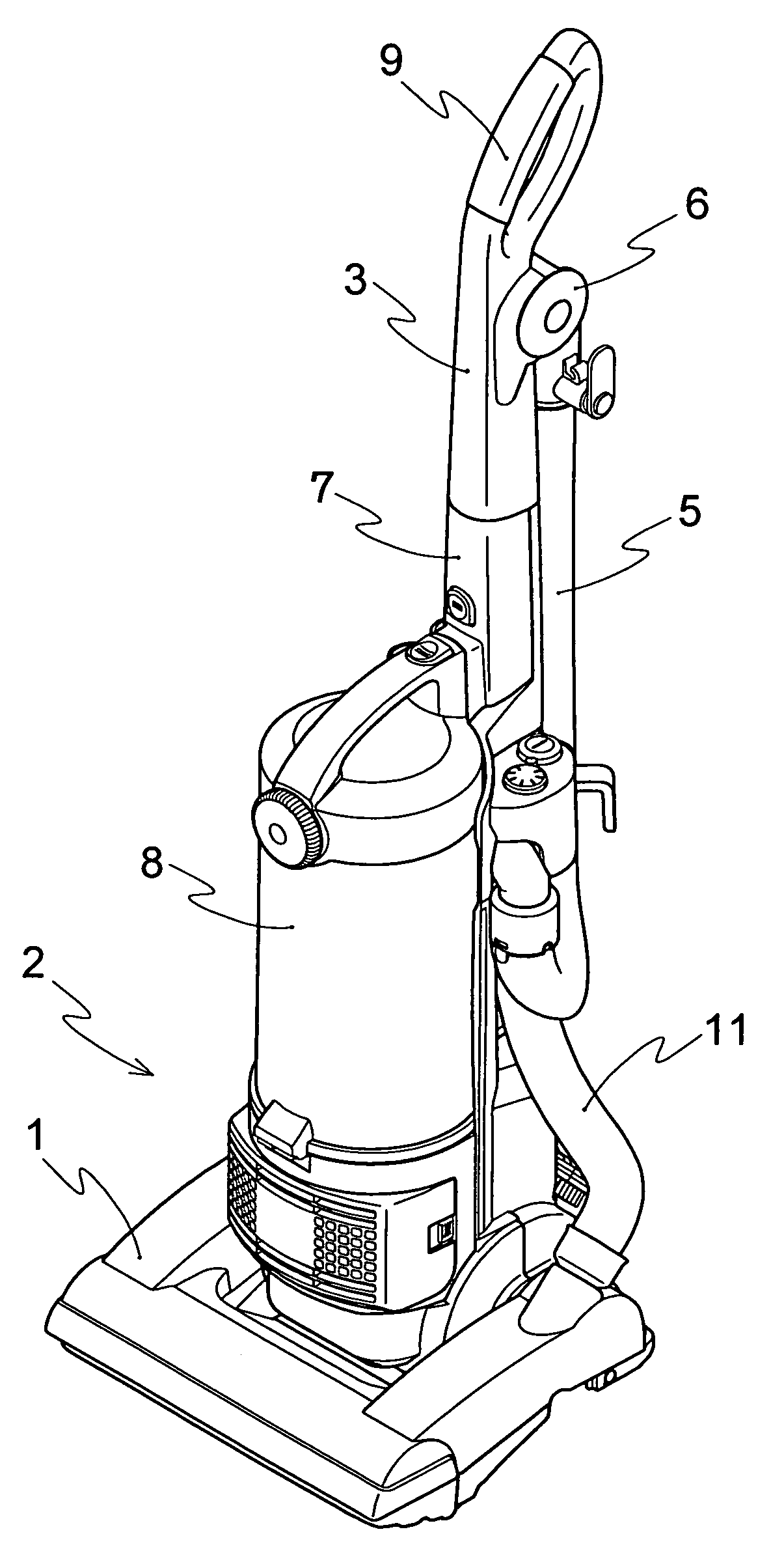
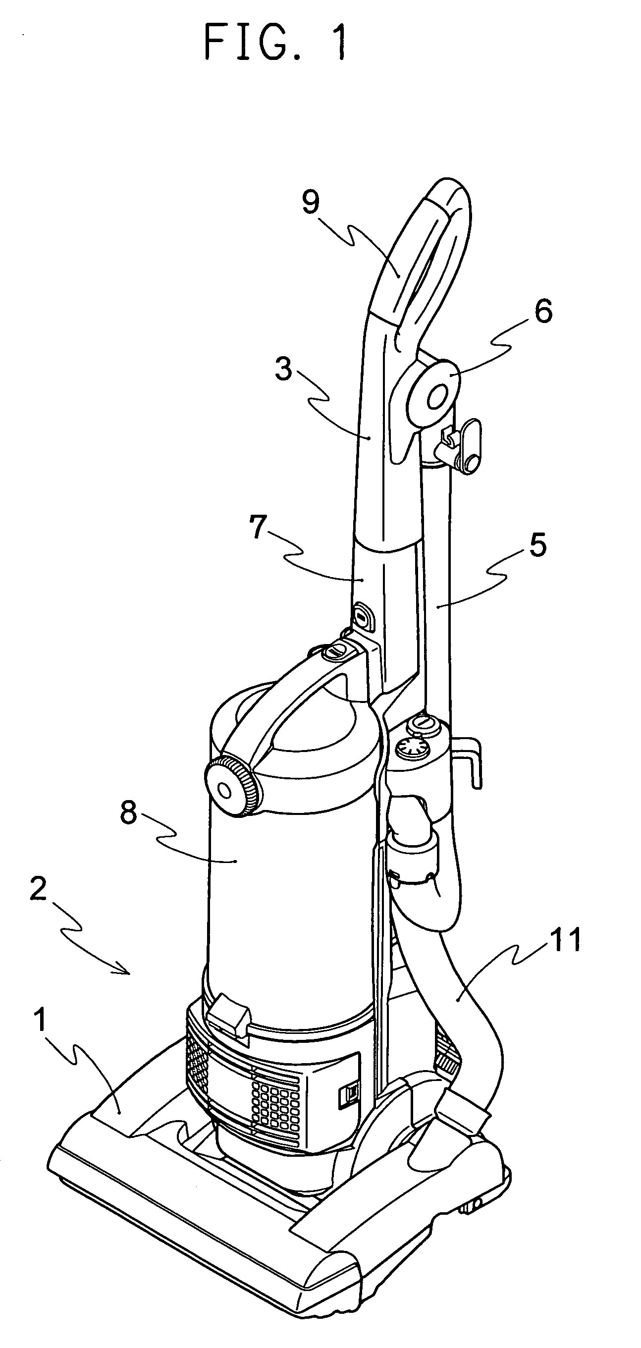
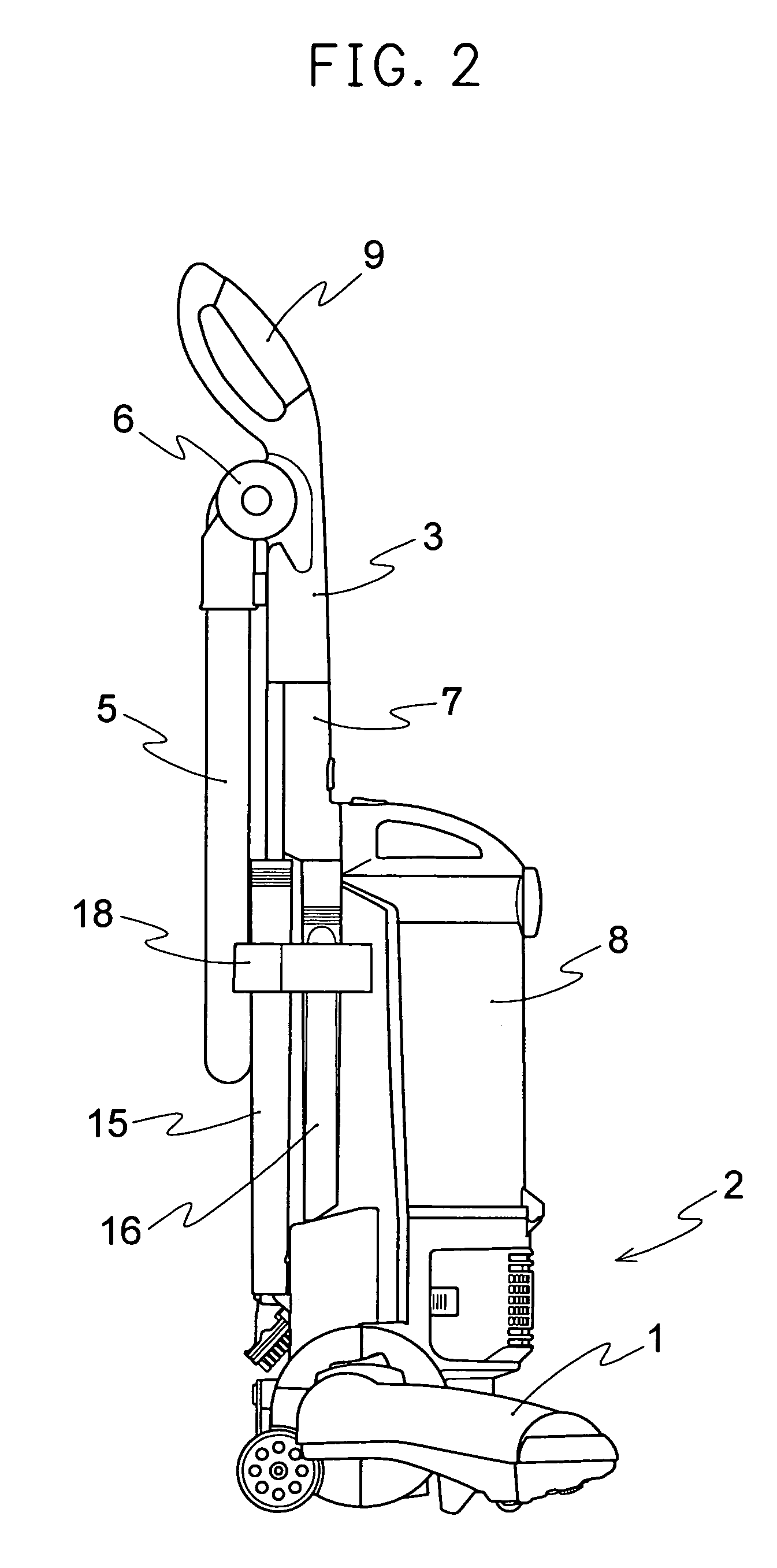
[0024]The upright type electric vacuum cleaner illustrated in FIGS. 1 to 6 is composed of a suction tool main body 1, a vacuum cleaner main body 2, a grip portion 3, a tip end side pipe 4 fixedly attached to the grip portion 3, a flexible hose 5, and a rotatable tube 6. A tip end portion of the tip end side pipe 4 is inserted into a tubular tip end side pipe supporting portion 7 of the vacuum cleaner main body 2 to be supported thereby in a freely attachable and detachable manner.

[0025]The suction tool main body 1 includes a suction inlet at a lower surface thereof and a rotating brush (not shown) inside of the suction inlet. The suction tool main body 1 is communicated with a rear portion 12 of the vacuum cleaner main body 2 through a connecting hose 11.

[0026]An electric air blower 10 is incorporated in the vacuum cleaner main body 2, and a dust box 8 is provid...


PUM


Abstract

An electric vacuum cleaner including a vacuum cleaner main body, a suction tool main body connected to the vacuum cleaner main body and having an suction inlet which is open at a lower surface thereof, a dust box connected to the vacuum cleaner main body, and a grip portion for operating the vacuum cleaner main body. The suction tool main body, an interior of the vacuum cleaner main body, the grip portion and the dust box are directly connected in this order such that circulation of air is permitted. The interior of the vacuum cleaner main body and the grip portion are connected in a freely attachable and detachable manner.

Description

CROSS-REFERENCE TO RELATED APPLICATION[0001]Priority is claimed under 35 U.S.C. 119 from Japanese patent application 2003-49360 filed Feb. 26, 2003.BACKGROUND OF THE INVENTION[0002]The present invention relates to an electric vacuum cleaner. More particularly, it relates to an upright type electric vacuum cleaner which can perform both, floor cleaning and handy cleaning using an attachment, wherein the electric vacuum cleaner is of simple arrangement which does not require a switching mechanism for switching between a flow path for ordinary use and a flow path for use with an attachment.[0003]An upright type electric vacuum cleaner, which is capable of cleaning not only floors but also places other than floors such as walls, is conventionally known. Such an upright type electric vacuum cleaner is provided with two flow paths, namely a main body flow path which extends from a suction tool main body to a dust chamber of a vacuum cleaner main body and a flow path for handy cleaning whi...

Claims


Application Information

Patent Timeline
IPC IPC(8): A47L5/28A47L9/24A47L5/32A47L9/00A47L9/12A47L9/32
CPCA47L5/32A47L9/122A47L9/325A47L9/327A63H3/00H04M1/725
Inventor YOSHIMI, KAZUYOSHIKAMATANI, KAZUMASAUEYAMA, SHUZOTAKAMI, HIROYUKINAKAI, KOUICHI
Owner SANYO ELECTRIC CO LTD
Why Eureka
Try Eureka