Zero-g offset identification of an accelerometer employed in a hard disk drive

a technology of accelerometer and hard disk drive, applied in the field of disk drives, can solve the problems of affecting the performance of the disk drive, annoying false indicators of free fall, and high artificially high thresholds, so as to reduce false indications of free fall and improve system reliability. the effect of reliability

Inactive Publication Date: 2008-04-01
MAXTOR
View PDF11 Cites 31 Cited by
  • Summary
  • Abstract
  • Description
  • Claims
  • Application Information

AI Technical Summary

Benefits of technology

[0017]It is desirable to have the most accurate threshold possible. Artificially high thresholds will tend to incorrectly park the actuator head when the disk drive is exposed to non-harmful vibrations, for example, when the disk drive is exposed to a periodic vibration of sufficient magnitude that are below the adjusted thresholds for a predetermined amount of time. False indicators of free fall are annoying and may affect the performance of the disk drive. By ensuring that the correct threshold is used, false indications of free fall will be minimized. In addition, by ensuring that the offset value is not artificially high, reliability in the system is increased, that is, drops will be quickly identified and the actuator arm and head will be timely secured.
[0018]Thus, as briefly mentioned above, it is one aspect of the present invention to provide a method for efficiently identifying the axis-specific offsets of an accelerometer and incorporating those into a system for detecting freefalls of a disk drive. In one embodiment of the present invention, a disk drive employing an accelerometer is placed horizontally upon a test table where the acceleration in the X and Y directions, i.e. the horizontal directions, should ideally be 0 g and the acceleration in the Z direction, i.e. vertical, should be 1 g. Of course, it should be understood that the orientation could be changed such that any two of the three

Problems solved by technology

Artificially high thresholds will tend to incorrectly park the actuator head when the disk drive is exposed to non-harmful vibrations, for example, when the disk drive is exposed to a periodic vib

Method used


Image

  • Zero-g offset identification of an accelerometer employed in a hard disk drive
  • Zero-g offset identification of an accelerometer employed in a hard disk drive
  • Zero-g offset identification of an accelerometer employed in a hard disk drive

Examples


Embodiment Construction

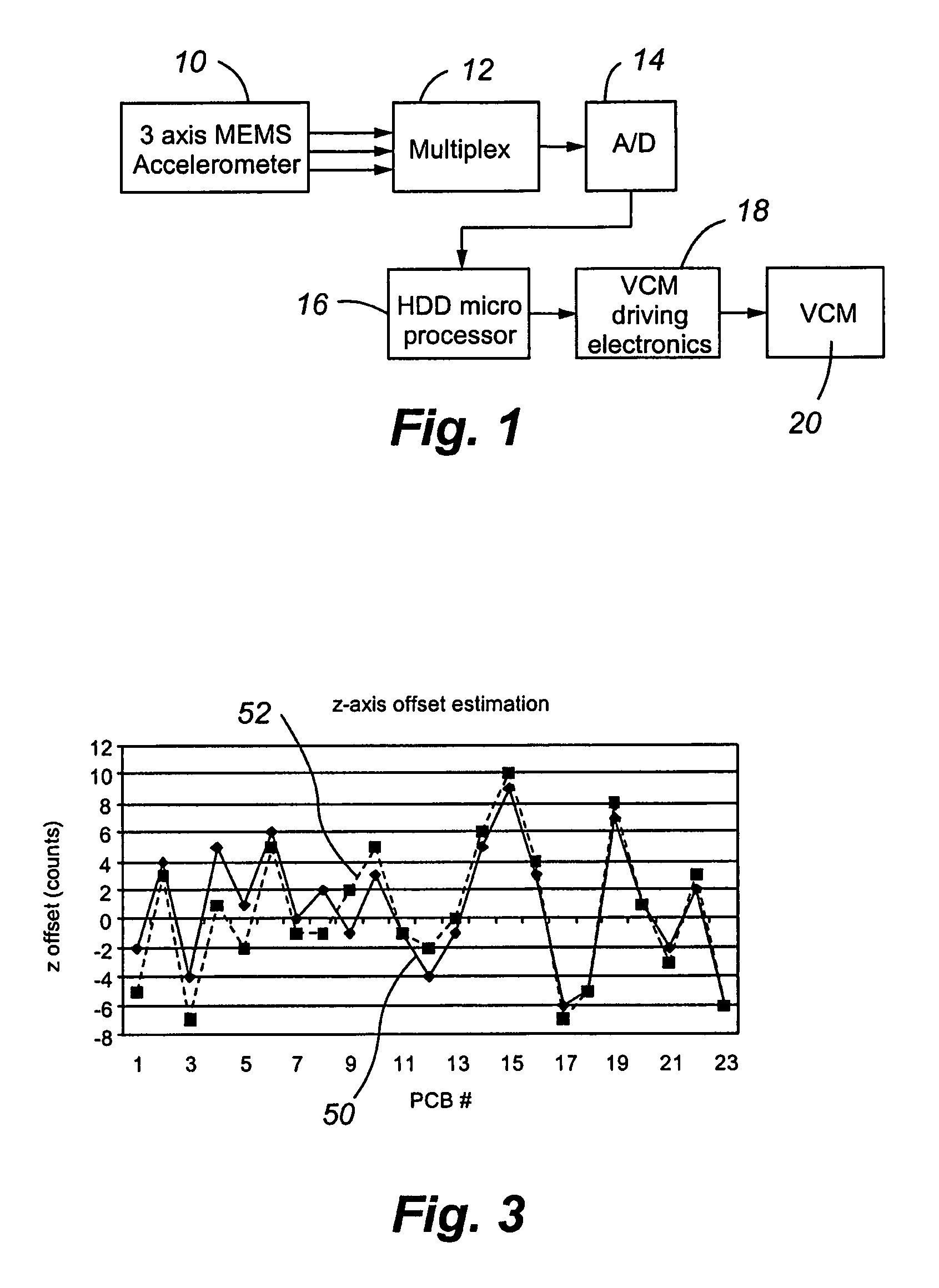
[0027]Referring now to FIG. 1, a block diagram illustrating a free fall detection / protection system is shown. This method is more fully described in co-pending patent application Ser. No. 11 / 292,831 entitled Mobile Hard Disk Drive Free Fall Detection and Protection, which is incorporated herein in its entirety. More specifically, a three-axis micro-electro-mechanical system accelerometer (MEMS) 10 is provided along with a multiplexer 12 and an analog to digital (A / D) converter 14. The three axis MEMS accelerometer 10 is designed to sense free fall acceleration in the X, Y, and Z directions and to feed the converted voltage into the multiplexer 12. The output voltage from the multiplexer 14 is then fed into the A / D converter 14 and then fed to a microprocessor 16. If the amount of acceleration exceeds a predetermined threshold, the microprocessor 16 directs a signal to the voice coil motor (VCM) driver electronics 18 instructing the VCM driver electronics to power the voice coil moto...


PUM


Abstract

A method is provided for identifying offsets of accelerometers integrated into hard disk drives. More specifically, often, disk drives employ accelerometers that constantly monitor the acceleration felt by the disk drive. Once the accelerations are less than a predetermined threshold, a free fall event is identified and an actuator arm that is generally positioned above the disk is placed in a safe location prior to impact. Accelerometers must be calibrated prior to use such that their inherent errors are identified and factored into the algorithm that identifies free fall. The method provided herein allows for the 0 g offset to be monitored without having to reorient the device being tested, thus saving time and money.

Description

CROSS-REFERENCE TO RELATED APPLICATIONS[0001]This application claims the benefit of U.S. Provisional Patent Application Ser. No. 60 / 632,915 and No. 60 / 633,052 filed Dec. 3, 2004, both of which are incorporated by reference in their entirety herein. This application is also related to U.S. patent application entitled “MOBILE HARD DISK DRIVE FREE FALL DETECTION AND PROTECTION,” which is further identified by Ser. No. 11 / 292,831 filed Dec. 2, 2005, which is incorporated by reference in its entirety herein.FIELD OF THE INVENTION[0002]The present invention relates generally to disk drives, and more particularly, a method and apparatus for protecting rotating media and read / write heads of the disk drive from mechanical shock events caused by an impact following a fall. More specifically, the present invention repositions the actuator arm off the disk or over a crash zone when free fall and / or tumbling motion is detected.BACKGROUND OF THE INVENTION[0003]Conventional disk drives employ a se...

Claims


Application Information

Patent Timeline
IPC IPC(8): G01P21/00
CPCG01P15/0891G01P15/18G01P21/00G11B19/043
Inventor FLYNN, WILLIAMGUO, WEIHEIMBAUGH, MARKLI, YUNFENG
Owner MAXTOR
Why Eureka
Try Eureka