Gearbox comprising an electromechanical actuator

a technology of electromechanical actuators and gearboxes, applied in mechanical devices, gearing details, gearing, etc., can solve problems such as requiring considerable structural space, and achieve the effect of reducing the necessary space and ensuring voltage supply

Inactive Publication Date: 2008-04-01
ZF FRIEDRICHSHAFEN AG
View PDF14 Cites 25 Cited by
  • Summary
  • Abstract
  • Description
  • Claims
  • Application Information

AI Technical Summary

Benefits of technology

[0007]An electromechanical transmission actuator of the invention has a first electric motor to exercise a selection motion of a shifting device in a transmission housing of a motor vehicle transmission, and it has a second electric motor to exercise a shifting motion of the shifting device. Sensor signals are received, processes and emitted as control signals to the electric motors in a sensor unit. The control unit can be wholly or partially integrated into the transmission actuator or also be constructed as an external control apparatus. The axis of rotation of the first electric motor and the axis of rotation of the second electric motor lie parallel to each other, which significantly reduces the necessary space required. The use of as many identical parts as possible, such as electric motors, recirculating ball screws or ball nuts for example, enable parallel allocation to one another. In an advantageous refinement, the transmission actuator includes a housing that is mounted on the transmission housing. It is, moreover, precisely mounted in such a way that a manual shifting module is arranged on the transmission housing. In this way, a continued use of a previously manually shifted transmission is also then possible as a shifted transmission automated with a transmission actuator without having to alter the transmission itself, indeed if need be, without having to remove the transmission from the motor vehicle. The flange surface between the transmission actuator and the transmission housing remains unchanged. In another advantageous refinement, the transmission actuator includes a housing that is integrated into the transmission housing. In this way, screwing the transmission actuator outside on the transmission housing and processing tight surfaces of the transmission actuator toward the outside is dispensed with. The housing is preferably made of sheet steel or pressure die cast aluminum. In an especially advantageous design, the first electric motor and the second electric motor are arranged, side by side, on a common side of the housing of the transmission actuator. In a further refinement, the first electric motor and the second motor are arranged on two sides of the housing of the transmission actuator lying opposite to each other. The electric motors are screwed to the housing on their front faces and sealed off from the housing on the flange surface. Each electric motor possesses an external plug contact through which signals are exchanged and voltage supply is assured. When using flattened motors, an especially small transmission actuator can be created by corresponding from the mounting position by twisting of the motor into the mounting position, as is necessary in certain mounting positions. Brushless servomotors, direct current motors, alternating current motors or stepping motors can be used as electric motors. Recirculating ball screws are used in order to use the rotary motion of the electric motors into a linear motion. In one design, one recirculating ball screw with a small incline each is provided for the selection motion and the shifting motion, which is respectively driven directly by an electric motor. In another design, one recirculating ball screw each with a large inclination is provided for the selection motion and the shifting motion, which is respectively driven by one of the electric motors through a gear reduction. Here bevel gears, spur gear, combinations of bevel gear and spur gear transmissions, worm drives or even lever transmissions are used. A thread, a spindle or a threaded spindle and a nut corresponding thereto can also be used as an alternative to the recirculating ball screw and the ball nut movable thereupon.

Problems solved by technology

The mechanism of motion of the shift finger in two axes of motion arranged perpendicular toward each other indeed corresponds to the selection and shifting specification on the basis of the manual shifting diagram as well as of the selection and the displacement of the respective shifter rod, but it also requires considerable structural space on the other hand.

Method used


Image

  • Gearbox comprising an electromechanical actuator
  • Gearbox comprising an electromechanical actuator
  • Gearbox comprising an electromechanical actuator

Examples


Embodiment Construction

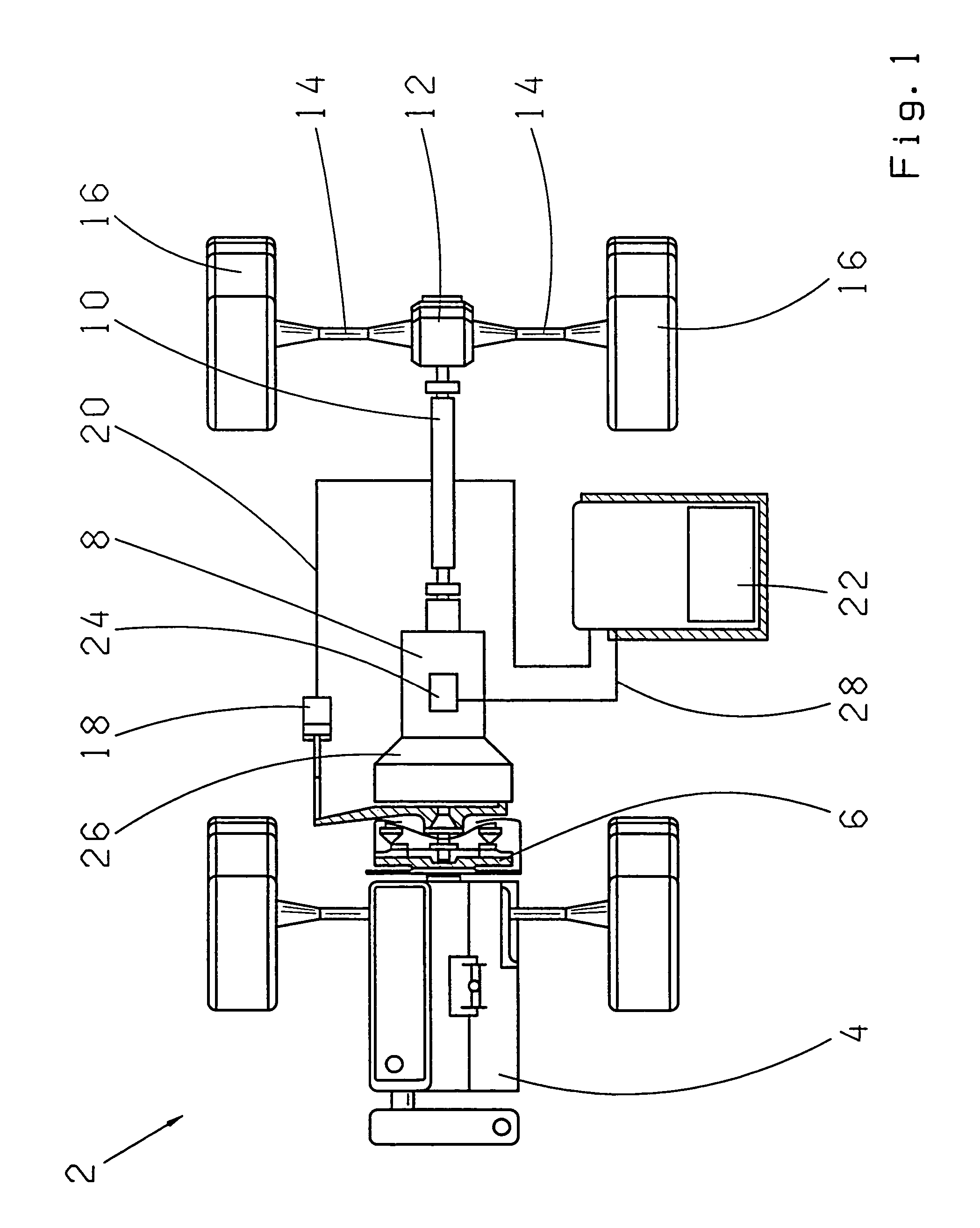
[0025]FIG. 1 illustrates a schematic representation of a motor vehicle 2 with a drive motor 4 which acts upon a transmission 8 through a friction clutch 6. The transmission 8 is connected with a differential 12 through an output shaft 10, which drives a motor vehicle wheel 16 through one half axle 14 each. The friction clutch 6 is activated by an actuator 18 which is connected with a control unit 22 through a signal line 20. The transmission 8 is activated by a transmission actuator 24 which is arranged on a housing 26 of the transmission and which is connected with the control unit 22 by a line 28.

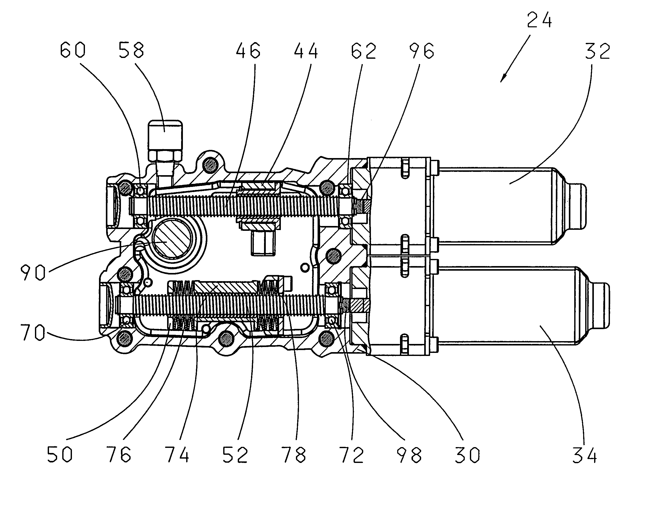
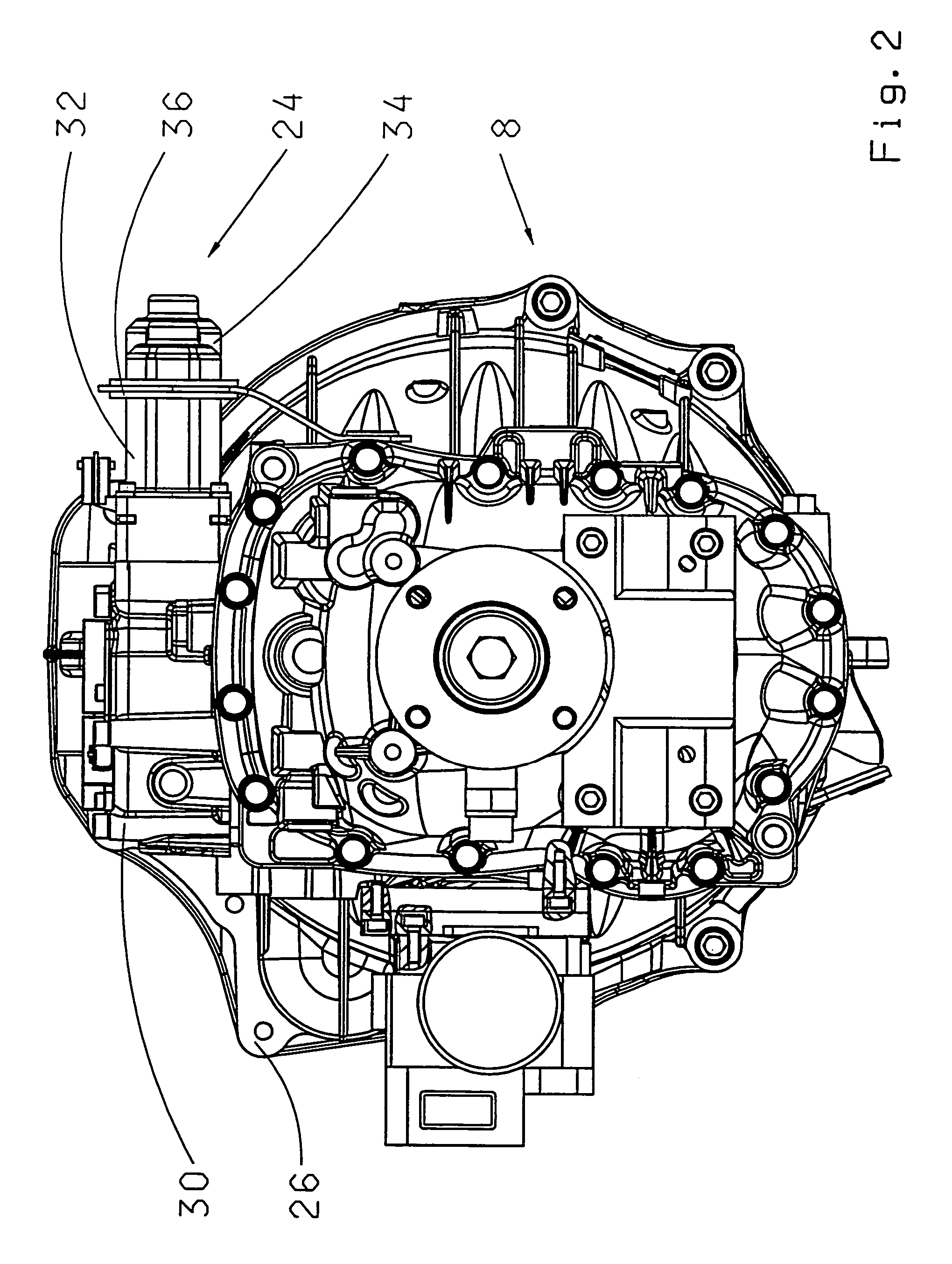
[0026]The transmission actuator 24 in an externally arranged housing 30 is mounted on the transmission housing 26 of the transmission 8 in FIG. 2. A first electric motor 32 and a second electric motor 34 lying beneath it, in this view, are arranged alongside each other on one side of the housing 30. A bracing sheet 36 embraces the two electric motors 32 and 34 and is fastened outside on t...


PUM


Abstract

A transmission (8) for a motor vehicle (2) with a housing (26) and a shifting apparatus arranged therein and with an electromechanical transmission actuator (24) with a first electric motor (32) for exercising a selection motion of the shifting device with a second electric motor (34) for exercising a shifting motion of the shifting apparatus and with a control unit (22) for receiving sensor signals, for processing the sensor signals and for emitting control signals to the electric motors (32, 34) the axis of rotation of the first electric motor (32) and the axis of rotation of the second electric motor (34) lie parallel to each other.

Description

[0001]This application is a national stage completion of PCT / EP02 / 09626 filed Aug. 29, 2002 which claims priority from German Application Ser. No. 101 43 325.5 filed Sep. 5. 2001.FIELD OF THE INVENTION[0002]The invention concerns an electromechanical transmission actuator and a transmission outfitted with an actuator of this type.BACKGROUND OF THE INVENTION[0003]Motor vehicles with automated gear boxes have been present on the market for a long time. Preferred use areas are motor vehicles in commercial use such as transporters and trucks. Passenger cars with sports applications or small cars have been increasingly outfitted with such transmissions in the recent past. The goal is to free the driver from shifting gears and generally to make a more comfortable and safe operation possible. Motor vehicles with such transmissions usually have two pedals as accelerator and brake. The clutch pedal can be dispensed with. A controller is available in the motor vehicle for selecting the mode o...

Claims


Application Information

Patent Timeline
Patent Type & Authority Patents(United States)
IPC IPC(8): F16H59/00F16H61/00F16H63/00F16H61/32F16H61/28
CPCF16H61/32F16H57/0006F16H57/027F16H59/68Y10T74/19251F16H2061/2823F16H2061/2884Y10T74/18576
Inventor SOMSCHOR, BERNDMIEHLE, FRANKSOMMER, NORBERTNEUENFELD, JURGENBUCHHOLD, OLIVER
Owner ZF FRIEDRICHSHAFEN AG
Why Eureka
Try Eureka