Ball screw device

a screw and ball technology, applied in mechanical equipment, gearing, hoisting equipment, etc., can solve the problems of large nut length, large thickness of end caps, and inability to achieve a reduction in nut members' size, so as to achieve the effect of reducing noise generation during the circulation

Active Publication Date: 2008-04-01
THK CO LTD
View PDF13 Cites 29 Cited by
  • Summary
  • Abstract
  • Description
  • Claims
  • Application Information

AI Technical Summary

Benefits of technology

[0016]Furthermore, according to the present invention, a synthetic resin pipe body is mounted to the nut main body to form a ball return hole, and when the return piece in which the direction switching passage is formed of synthetic resin, the non-load passage for endless circulation of the balls is entirely covered with synthetic resin, so that it is possible to minimize noise generation during the circulation of the balls as much as possible.

Problems solved by technology

However, as described above, in the conventional end cap type ball screw device, the end caps have scoop portions for dislodging the balls from the ball rolling groove of the screw shaft and direction switching passages for guiding the dislodged balls to the ball return hole, so that the thickness of the end caps must be rather large.
Thus, when the end caps are fixed to the end surfaces of the nut main body, the total length of the nut member is rather large for the magnitude of the load applied, thus making it impossible to achieve a reduction in the size of the nut member.
Further, a great resistance is offered to the circulation of the balls 107, which leads to a limitation in the high speed feeding of the movable body.
Further, the balls 107 and the end caps 103 generate collision sound, which leads to a problem of noise during use.

Method used


Image

  • Ball screw device
  • Ball screw device
  • Ball screw device

Examples


first embodiment

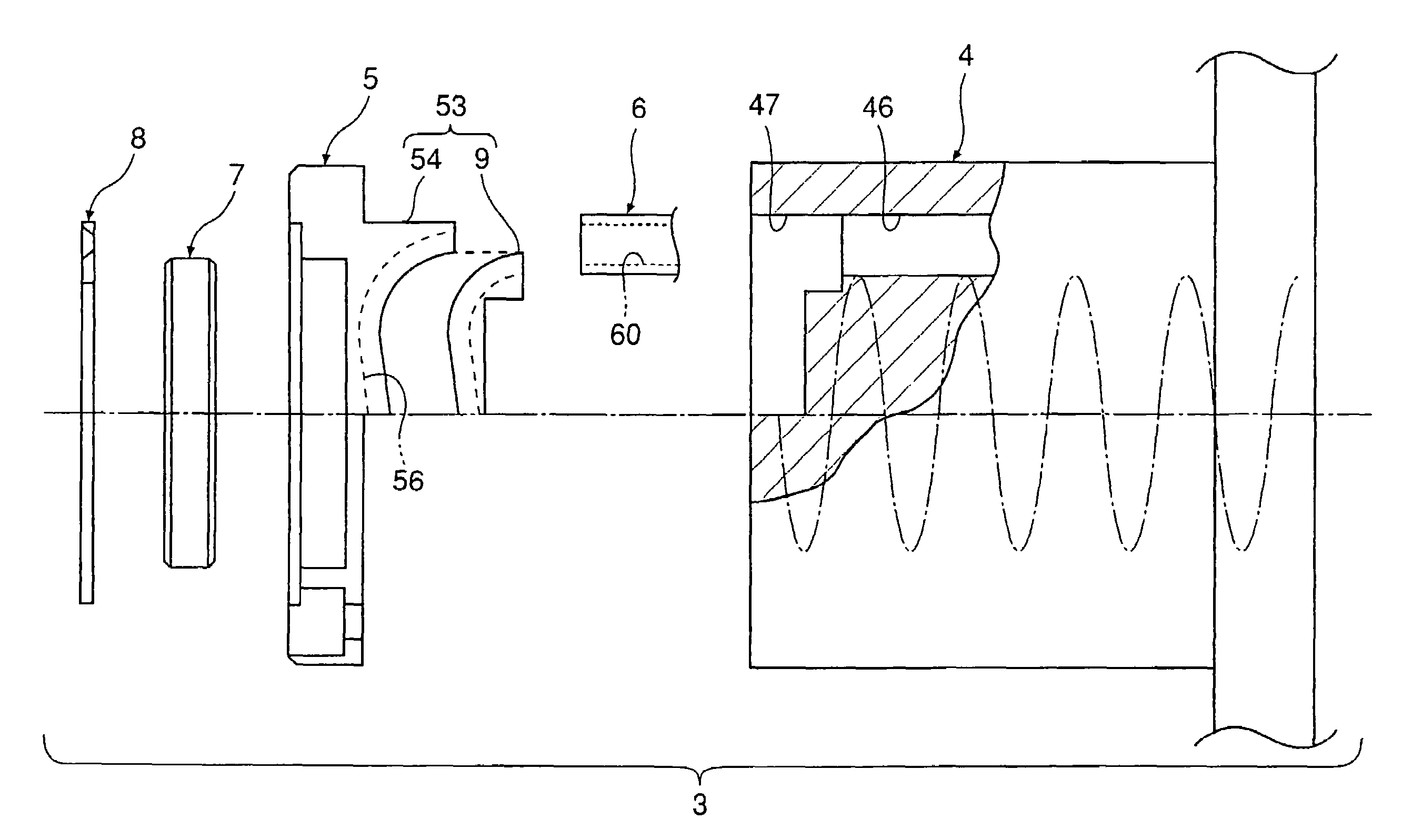
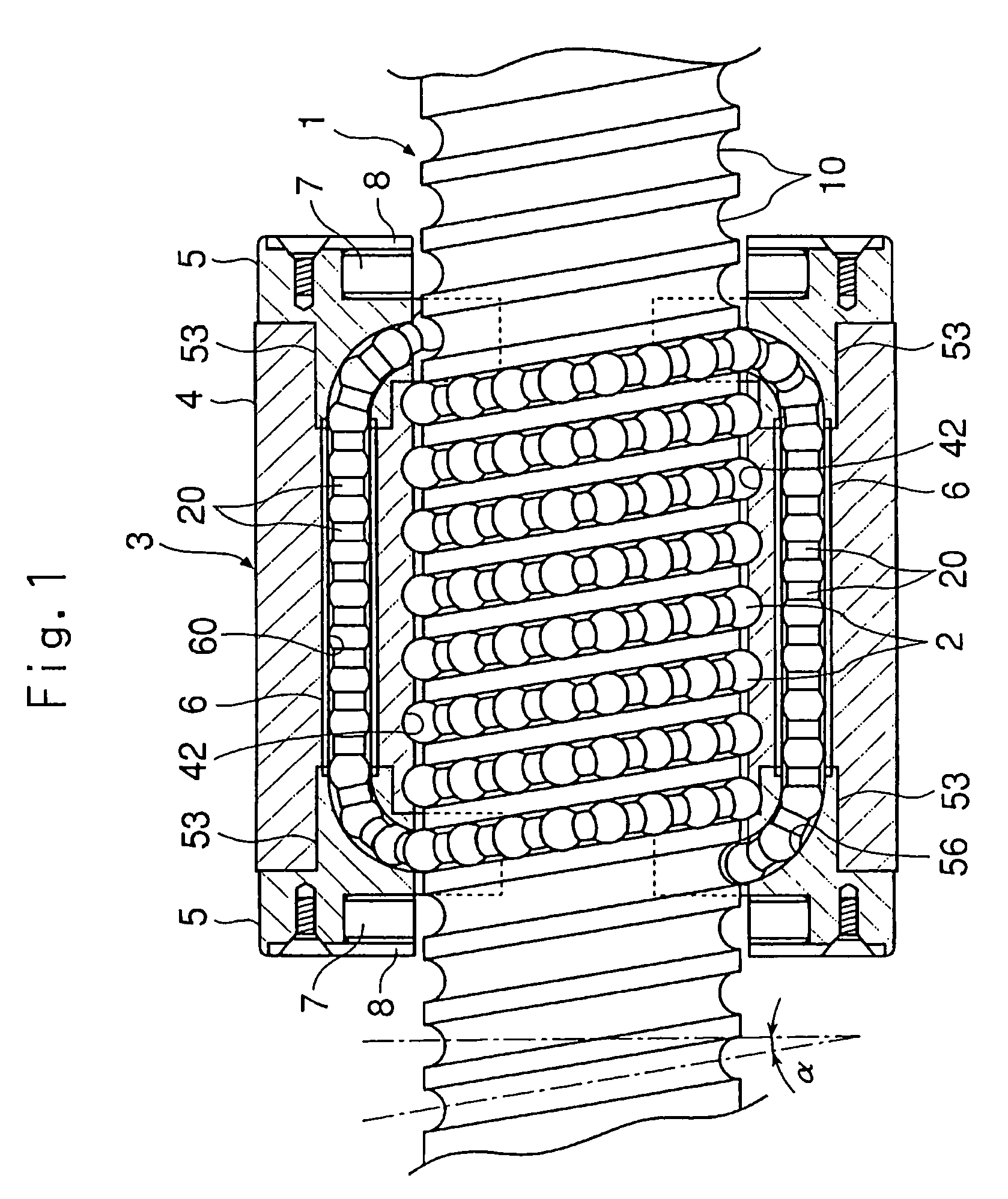
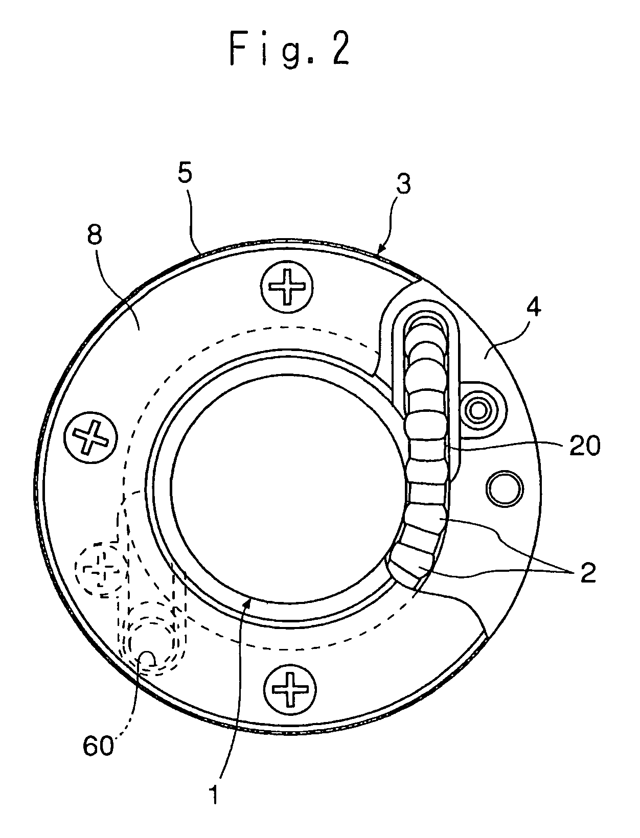
[0035]FIGS. 1 and 2 show a ball screw device according to the present invention. This ball screw device is composed of a screw shaft 1 whose outer peripheral surface has a spiral ball rolling groove 10 formed at a predetermined lead, and a nut member 3 threadedly engaged with the screw shaft 1 through the intermediation of a number of balls 2 and equipped with an endless circulation route for the balls 2, wherein the nut member 3 makes a movement in the axial direction of the screw shaft 1 through relative rotation of the screw shaft 1 and the nut member 3. Further, the screw shaft 1 has two streaks of ball rolling grooves 10, and the nut member 3 also has two endless circulation routes of the balls 2.

[0036]In this ball screw device, spacers 20 are provided between the balls 2 adjacent to each other in the endless circulation routes, thus preventing the balls 2 from coming into direct contact with each other. The spacers 20 are disc-like members formed of synthetic resin, each havin...

second embodiment

[0050]FIG. 13 shows a ball screw device according to the present invention.

[0051]While in the first embodiment described above the first pieces 54 forming the return pieces 53 are formed integrally with the cover plates 5, in the second embodiment, the first pieces 54 and the cover plates 5 are separated from each other, and the return pieces 53 are fit-engaged with the recesses 47 of the nut main body 4 without fixing the cover plates 5 to the nut main body 4. Otherwise, this embodiment is of the same construction as the first embodiment, so that the components that are the same as those of the first embodiment are indicated by the same reference numerals in FIG. 13, and a detailed description of such components will be omitted.

[0052]FIG. 14 is a perspective view showing the return piece 53 adopted in the second embodiment. FIG. 15 is a perspective view showing the return piece 53 as divided into the first piece 54 and the second piece 9. While the first piece 54 and the second pie...


PUM


Abstract

The invention relates to a ball screw device in which a screw shaft and a nut member are threadedly engaged with each other through a number of balls. In such a ball screw device, an inner surface of a cover plate contacting an end surface of a nut main body is provided with a projecting return piece adapted to be fit-engaged with a recess cut in an inner peripheral surface of the nut main body, the return piece being provided with a scoop portion for dislodging the balls from the ball rolling groove of the screw shaft and a direction switching passage for guiding the dislodged balls to the entrance of a ball return hole. The projecting return piece is divided into a first piece formed integral with the cover plate and a second piece fixed to the first piece by a curved plane including the center line of the direction switching passage.

Description

TECHNICAL FIELD[0001]The present invention relates to a ball screw device in which a screw shaft and a nut member are threadedly engaged with each other through the intermediation of a number of balls and, more particularly to an improved ball screw device in which the nut member is equipped with a so-called end cap type ball circulation structure.BACKGROUND ART[0002]Conventionally, a ball screw device in which a screw shaft and a nut member are threadedly engaged with each other through the intermediation of a number of balls is well known. In such a ball screw device, a spiral ball rolling groove formed in an outer peripheral surface of the screw shaft and a spiral load rolling groove formed in an inner peripheral surface of the nut member face each other to form a load passage, with balls effecting load application between the screw shaft and the nut member while rolling in this load passage. Further, the nut member is equipped with a non-load passage for circulating balls having...

Claims


Application Information

Patent Timeline
Patent Type & Authority Patents(United States)
IPC IPC(8): F16H25/22F16C33/37
CPCF16C33/3706F16H25/2219Y10T74/19767Y10T74/19749Y10T74/19772F16H25/22
Inventor NISHIMURA, KENTAROUYOSHIDA, AKIMASANIWA, HIROSHI
Owner THK CO LTD
Why Eureka
Try Eureka