
Powdered graphite applicator

a technology of applicators and graphite, which is applied in the direction of machines/engines, drip or splash lubrication, liquid transfer devices, etc., can solve the problems of dangerously close cover or lid of the graphite storage compartment to the driving ring of the drum, drag and eventual failure, and difficult filling of the compartmen

Active Publication Date: 2008-04-01
PRECISION ROTARY EQUIP
View PDF4 Cites 0 Cited by
  • Summary
  • Abstract
  • Description
  • Claims
  • Application Information

AI Technical Summary

Benefits of technology

"The present invention is an improved powdered graphite applicator that lubricates the support rollers of a rotating drum. The applicator includes a container for holding powdered graphite, with an internal plate and a screen for controlling the flow of powder. The container also has a pivotal gate for controlling the flow of powder. The technical effect of this invention is to provide a more efficient and controlled method for applying powdered graphite to a roller surface, which improves the performance and durability of the rollers."

Problems solved by technology

First, conventional applicators dispense the powder graphite through small holes which have a tendency to become clogged.
Also, when used with a rotating drum dryer, the heat from the dryer causes warpage of the control piston inside the applicator, causing drag and eventual failure.
Furthermore, with an applicator such as disclosed in the U.S. Pat. No. 5,421,431, the cover or lid for the graphite storage compartment is dangerously close to the driving ring of the drum and makes filling of the compartment difficult.
The relatively large number of moving and machined components in the conventional applicator also leads to increased manufacturing costs.
Some applicators apply graphite using air, which dispenses the graphite not only on the rollers but also into the air resulting in a great waste of graphite.
Also, silicate in the powdered graphite is an air born health hazard.

Method used


Image

  • Powdered graphite applicator
  • Powdered graphite applicator
  • Powdered graphite applicator

Examples


Embodiment Construction

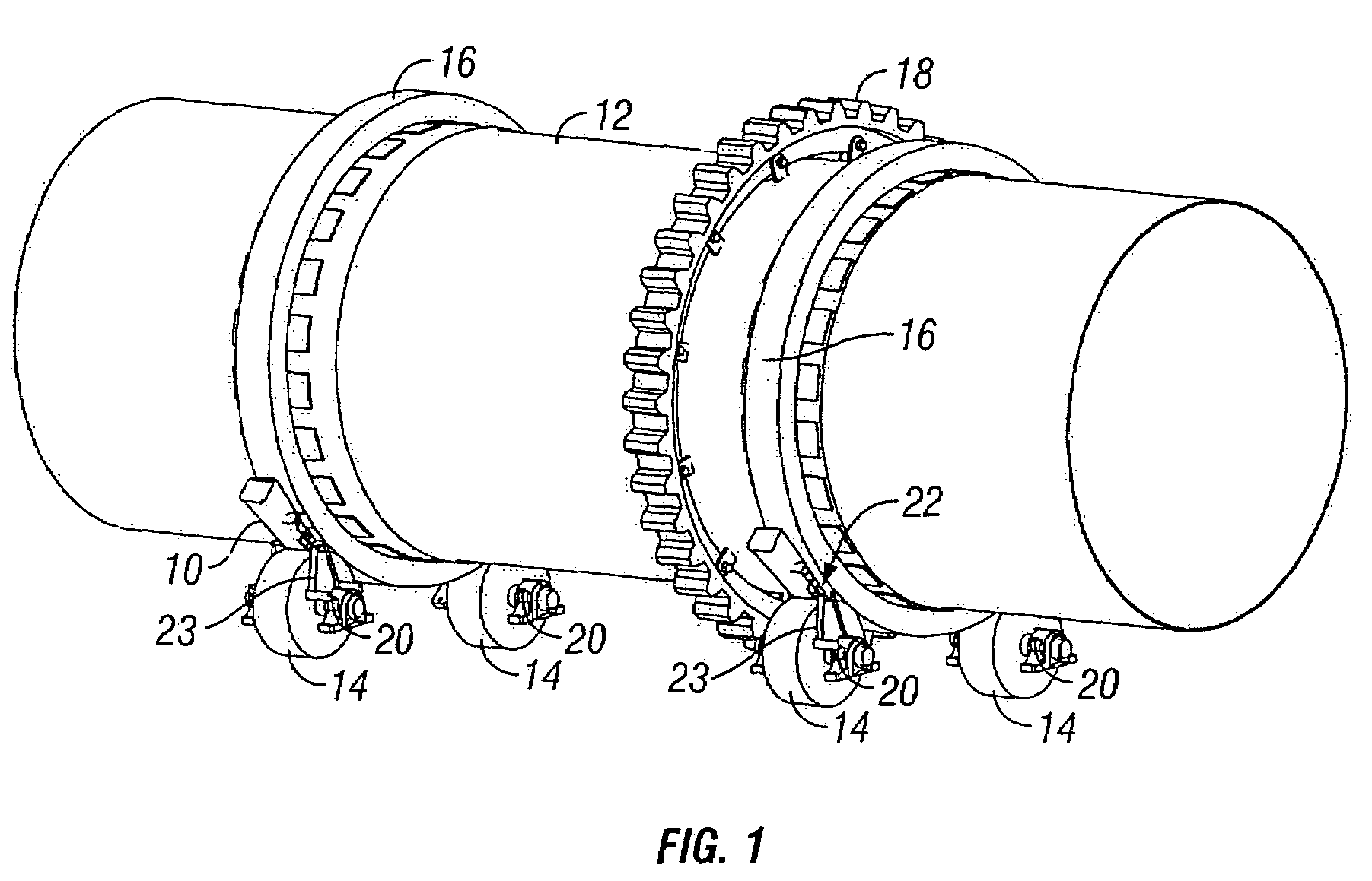
[0019]FIG. 1 shows the graphite applicator 10 of the present invention as used on a rotatable drum 12. The drum 12 is supported by two pairs of rollers or trunnion wheels 14 which engage respective drum rings 16 extending around the periphery of the drum 12. The drum 12 also includes a drive ring 18 which is driven by a motor (not shown) with a meshing gear or chain. The structure of the drum 12 and rollers 14 is conventional, and do not constitute a part of the present invention.

[0020]One graphite applicator 10 is utilized for each drum ring 16. The graphite applicator 10 is mounted to the pillow block bearings 20 of one of the rollers 14 adjacent a pinch point 22 between the rollers 14 and the drum 12. If the support rollers are adjusted via the bearings 20, the applicator 10 is also automatically adjusted to maintain top performance of the applicator 10 in lubricating the rollers 14 and support rings 16. The graphite applicator 10 is mounted to the roller bearings 20 via mounting...


PUM


Abstract

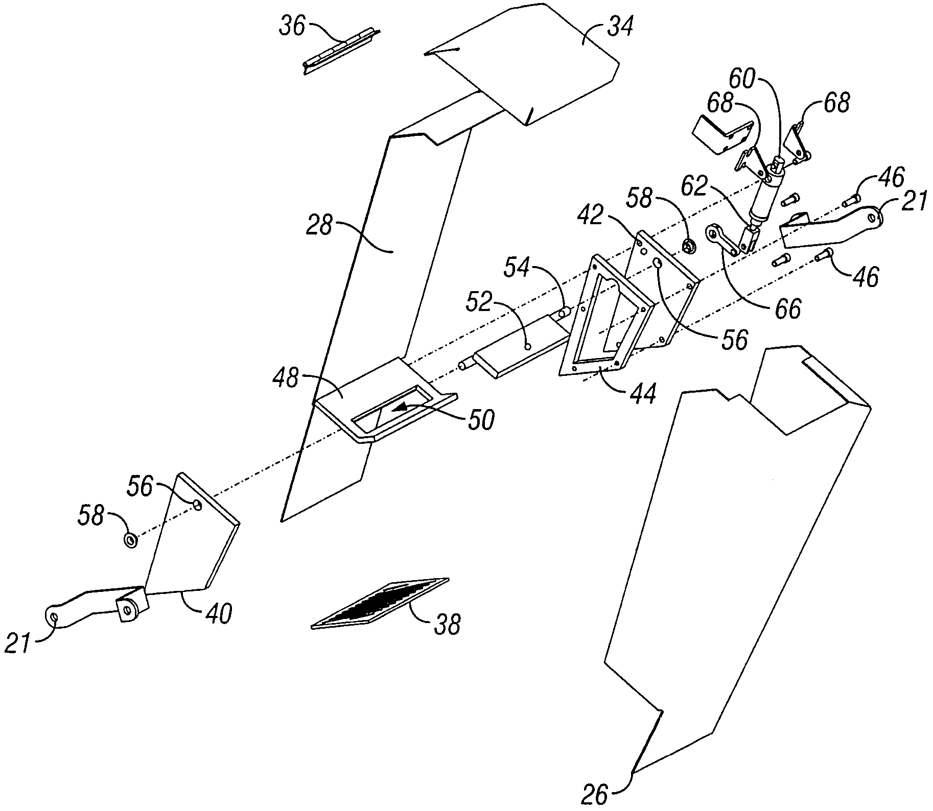
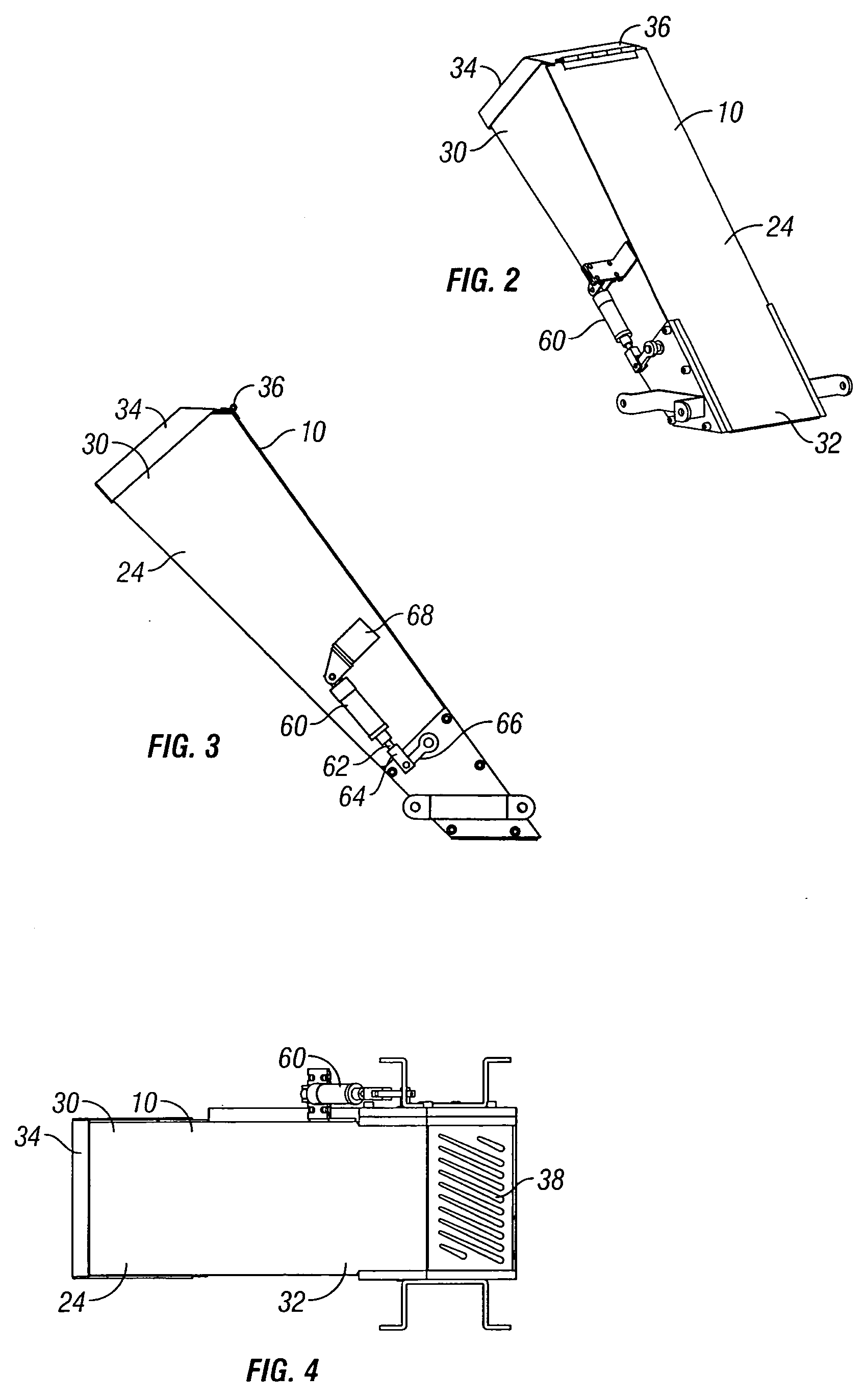
The powdered graphite applicator includes a container with a lid at the upper end and a screen at the lower end. A plate is provided inside the container to define the bottom of the graphite chamber. The plate has an enlarged opening which is normally closed by a gate. The gate can be periodically opened to allow graphite to pass through the plate opening, and then to fall from the plate through the screen and onto the surface of an adjacent roller of a rotatable drum. Movement of the gate is controlled by a cylinder with an extensible arm. Extension and retraction of the cylinder arm is automatically controlled by a solenoid and a programmed controller.

Description

BACKGROUND OF THE INVENTION[0001]Rotating drums are used for various purposes, such as drying kilns and spray coating machines for coating products such as snack foods, seeds, and pharmaceuticals. The drums are supported on rollers or trunnion wheels and typically are rotated by a motor-driven gear or chain. Powder graphite is often used to lubricate the surface of the drum rollers and the riding ring extending around the drum. One example of a powdered graphite applicator is disclosed in U.S. Pat. No. 5,421,431. Conventional graphite applicators, such as disclosed in the U.S. Pat. No. 5,421,431 have several problems. First, conventional applicators dispense the powder graphite through small holes which have a tendency to become clogged. Also, when used with a rotating drum dryer, the heat from the dryer causes warpage of the control piston inside the applicator, causing drag and eventual failure. Furthermore, with an applicator such as disclosed in the U.S. Pat. No. 5,421,431, the ...

Claims


Application Information

Patent Timeline
Patent Type & Authority Patents(United States)
IPC IPC(8): F16N27/00F16N15/02
CPCF16N15/02
Inventor LAURITO, PATRICK J.
Owner PRECISION ROTARY EQUIP
Learn More