Toner

a technology of toner and nozzle, applied in the field of toner, can solve the problems of affecting the mechanical strength of toner is apt to decrease, and the contamination of the fixing-receiving sheet by the offset phenomenon, and achieves the effects of improving the performance of toner, and improving the durability of toner

Active Publication Date: 2008-04-01
CANON KK
View PDF27 Cites 32 Cited by
  • Summary
  • Abstract
  • Description
  • Claims
  • Application Information

AI Technical Summary

Benefits of technology

[0020]That is, an object of the present invention is to provide a toner having superior development durability, low-temperature fixing performance and high-temperature anti-offset properties even in a high-speed development system.
[0021]Another object of the present invention is to provide a toner prevented from causing adhesion (melt adhesion) of toner to developer carrying members and melt adhesion of toner to photosensitive members even in a high-speed development system, and also from causing spots around line images and ghost.

Problems solved by technology

However, since the heat roller surface and the toner image come into contact with each other under application of pressure, there is a problem of high-temperature offset such that part of the toner image may adhere, and be transferred, to the fixing roller surface, and transferred again to the next fixing-receiving sheet to cause an offset phenomenon to contaminate the fixing-receiving sheet.
The low-temperature fixing performance is desired to be further improved, but when improving the low-temperature fixing performance, problems are raised such that the mechanical strength of toner is apt to lower, and development durability tends to lower and cause problems such as adhesion (melt adhesion) of toner to developer carrying members and melt adhesion of toner to photosensitive members.
However, on the other hand, they have the disadvantage of causing the offset phenomenon at a high temperature.
Also, the polyester resin is difficult to pulverize in a process involving the pulverization step and is disadvantageous in respect of productivity.
However, the molecular weight of the binder resin in its molecular weight distribution is reduced in an attempt to lower the temperature at which the melt viscosity begins to lower, with the result that necessary release effect is not obtained.
Even if a release agent is used with vinyl resins having reduced molecular weight in order to achieve low-temperature fixing, the melted resins themselves have so low viscosity as to make it difficult to obtain the necessary release effect.
Also, the cutting of polymer molecular chains may generate heat to cause the temperature rise of the polymer itself at the time of melt kneading, thereby raising such a problem that it is unable to achieve the sufficient dispersion state of the components contained in the toner particles.
In addition, when using such a cross-linked resin, the resin has high viscosity to cause coarse particles in producing toner particles.
As a result, the toner tends to bring about faulty images due to sleeve coat non-uniformity, which is remarkable especially in a high-speed development system.
Thus, under existing circumstances, there is no toner which can satisfactorily achieve all the space saving, high speed and energy saving.

Method used


Image

  • Toner
  • Toner
  • Toner

Examples


examples

[0325]The fundamental constitution and characteristic features of the present invention have been described above. In the following, the present invention is described in greater detail by giving Examples. However, they should not be construed to limit embodiments of the present invention.

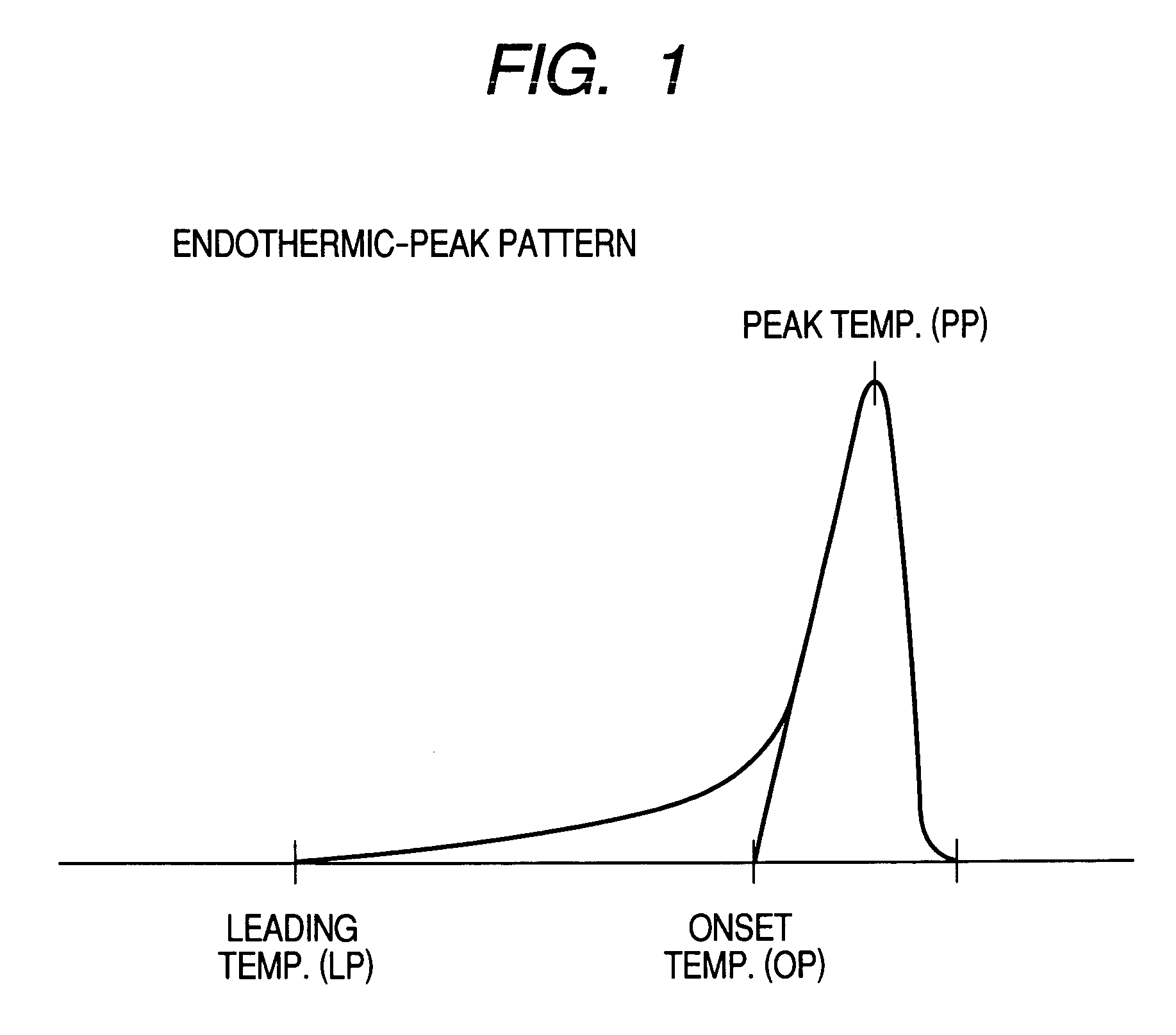
[0326]Waxes (a) and (b) used in Examples and Comparative Example are shown in Tables 1 and 2. Resin production processes are shown below. The results of measurement by DSC of the wax (a) are shown in FIG. 1.

Production Example A-1 of High-Molecular Weight Component

[0327]

(by weight)Styrene80.0partsn-Butyl acrylate18.0partsMethacrylic acid2.0parts2,2-Bis(4,4-di-t-butylperoxycyclohexyl)propane0.8part

[0328]In a four-necked flask, while stirring 200 parts by weight of xylene, the inside of the container was sufficiently displaced with nitrogen and was heated to 120° C., and thereafter the above materials were dropwise added over a period of 4 hours. Further, with retention for 10 hours under reflux of xy...

production example b-1

of Vinyl Resin Having Carboxyl Group

[0330]

(by weight)High-Molecular Weight Component A-130partsStyrene56.5partsn-Butyl acrylate12.8partsMethacrylic acid0.7partDi-tert-butyl peroxide1.4parts

[0331]200 parts by weight of xylene was introduced into an autoclave, and nitrogen gas was fed into it to sufficiently carry out deaeration. Next, this vessel was sealed, followed by heating to 200° C. Keeping this temperature, among materials in the above formulation, compounds other than High-Molecular Weight Component A-1 were dropwise added into the xylene over a period of 4 hours. Further, with retention under reflux of xylene for 1 hour, polymerization was completed. Then, High-Molecular Weight Component A-1 was added to the xylene solution, and these were thoroughly mixed to prepare a resin solution containing Resin B-1. Physical properties of Resin B-1 are shown in Table 4.

production examples b-2

to B-5 of Vinyl Resin Having Carboxyl Group

[0332]Resin solutions containing respectively Resins B-2 to B-5 were obtained in the same manner as in Production Example B-1 except that in Production Example B-1 the formulation was changed as shown in Table 4. Physical properties of Resins B-2 to B-5 are shown in Table 4.


PUM

PropertyMeasurementUnit
viscosityaaaaaaaaaa
temperatureaaaaaaaaaa

Abstract

A toner is disclosed including toner particles containing a binder resin and a colorant. The binder resin contains a vinyl resin. In the high-temperature GPC-RALLS-viscometer analysis of the o-dichlorobenzene-soluble matter of the toner, a weight-average molecular weigh of absolute molecular weights measured with a viscosity detector is in a specific range. In the o-dichlorobenzene-soluble matter, a component with the absolute molecular weight of 10,000 or less and a component with the absolute molecular weight of 1,000,000 or more are present in specific proportions, respectively. The intrinsic viscosity of the toner is in a specific range.

Description

BACKGROUND OF THE INVENTION[0001]1. Field of the Invention[0002]This invention relates to a toner used in image forming processes such as electrophotography, electrostatic recording, magnetic recording and toner jet recording.[0003]2. Related Background Art[0004]In electrophotography, conventionally using photoconductive materials, an electrostatic latent image is formed on a photosensitive member by various means, subsequently developed by the use of a toner to form a toner image, and the toner image is transferred to a transfer material such as paper as needed, followed by fixing by the action of heat, pressure, heat-and-pressure or solvent vapor to form a fixed image.[0005]As a method for fixing the toner image to a sheet such as paper, which is the above final step, the most commonly available method at present is a pressure-and-heating system making use of a heat roller. According to this method, the surface of the heat roller and the toner image on the fixing-receiving sheet (...

Claims


Application Information

Patent Timeline
Patent Type & Authority Patents(United States)
IPC IPC(8): G03G9/08G03G9/087
CPCG03G9/08704G03G9/08706G03G9/08708G03G9/08711G03G9/08782G03G9/08793G03G9/08795G03G9/08797
Inventor MORIBE, SHUHEIOKUBO, NOBUYUKIONUMA, TSUTOMUABE, SHINICHIRONISHIKAWA, KOJI
Owner CANON KK
Why Eureka
Try Eureka