Primary-side controlled switching regulator

a switching regulator and side-controlled technology, applied in the direction of power conversion systems, instruments, dc-dc conversion, etc., can solve the problems of inaccuracy of output voltage and output current control, and achieve the effect of improving load regulation

Active Publication Date: 2008-04-01
FAIRCHILD SEMICON CORP
View PDF4 Cites 107 Cited by
  • Summary
  • Abstract
  • Description
  • Claims
  • Application Information

AI Technical Summary

Problems solved by technology

However, the drawback of the aforementioned conventional primary side control schemes is the inaccurate control of the output voltage and output current.

Method used


Image

  • Primary-side controlled switching regulator
  • Primary-side controlled switching regulator
  • Primary-side controlled switching regulator

Examples


Embodiment Construction

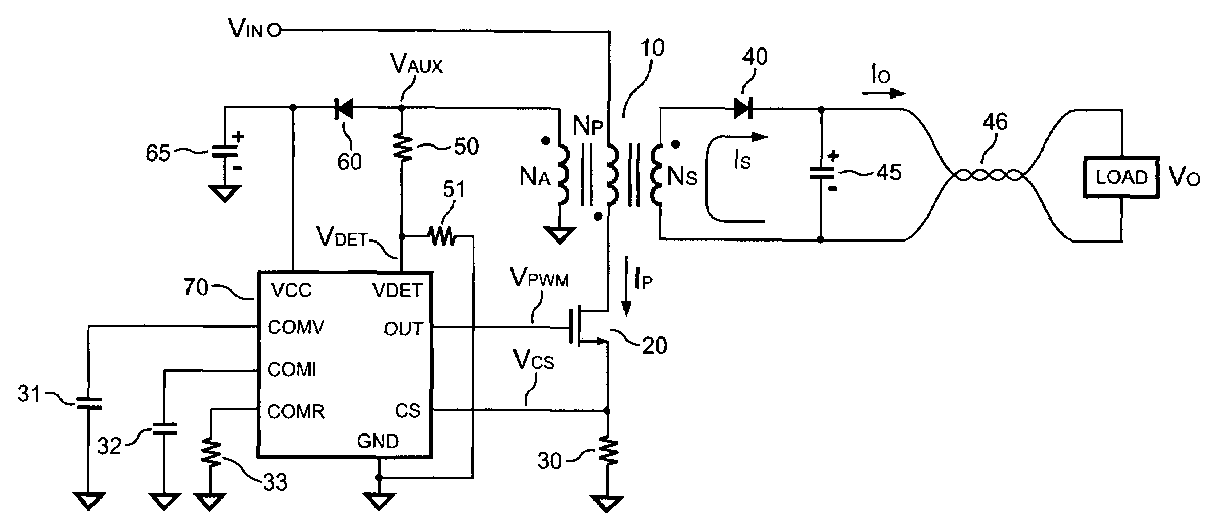
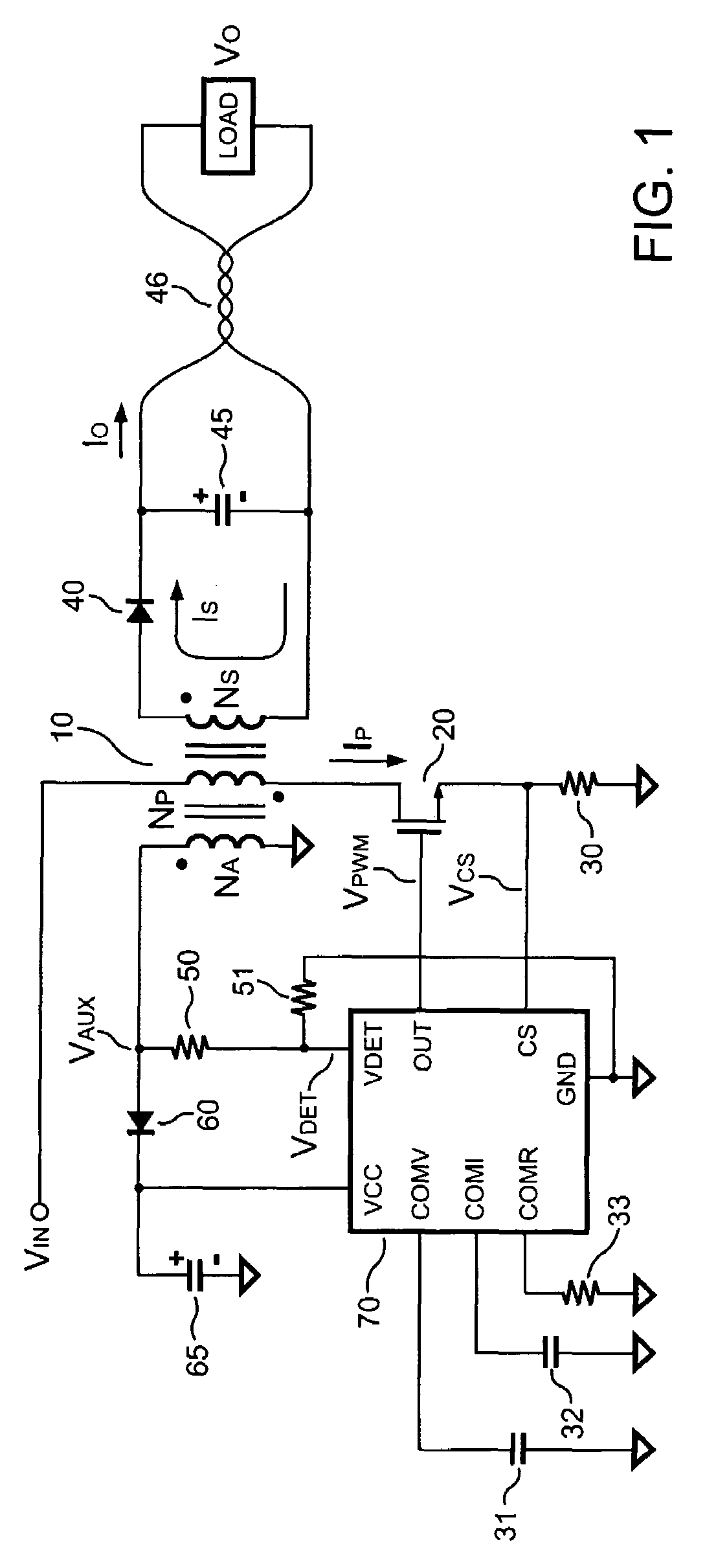
[0020]FIG. 1 illustrates a conventional primary-side controlled switching regulator. The switching regulator includes a transformer 10 having an auxiliary winding NA, a primary winding Np, and a secondary winding NS. To regulate an output voltage VO and an output current IO of the switching regulator, A switching signal VPWM is generated by a control circuit 70 to a transistor 20 for switching a transformer 10.

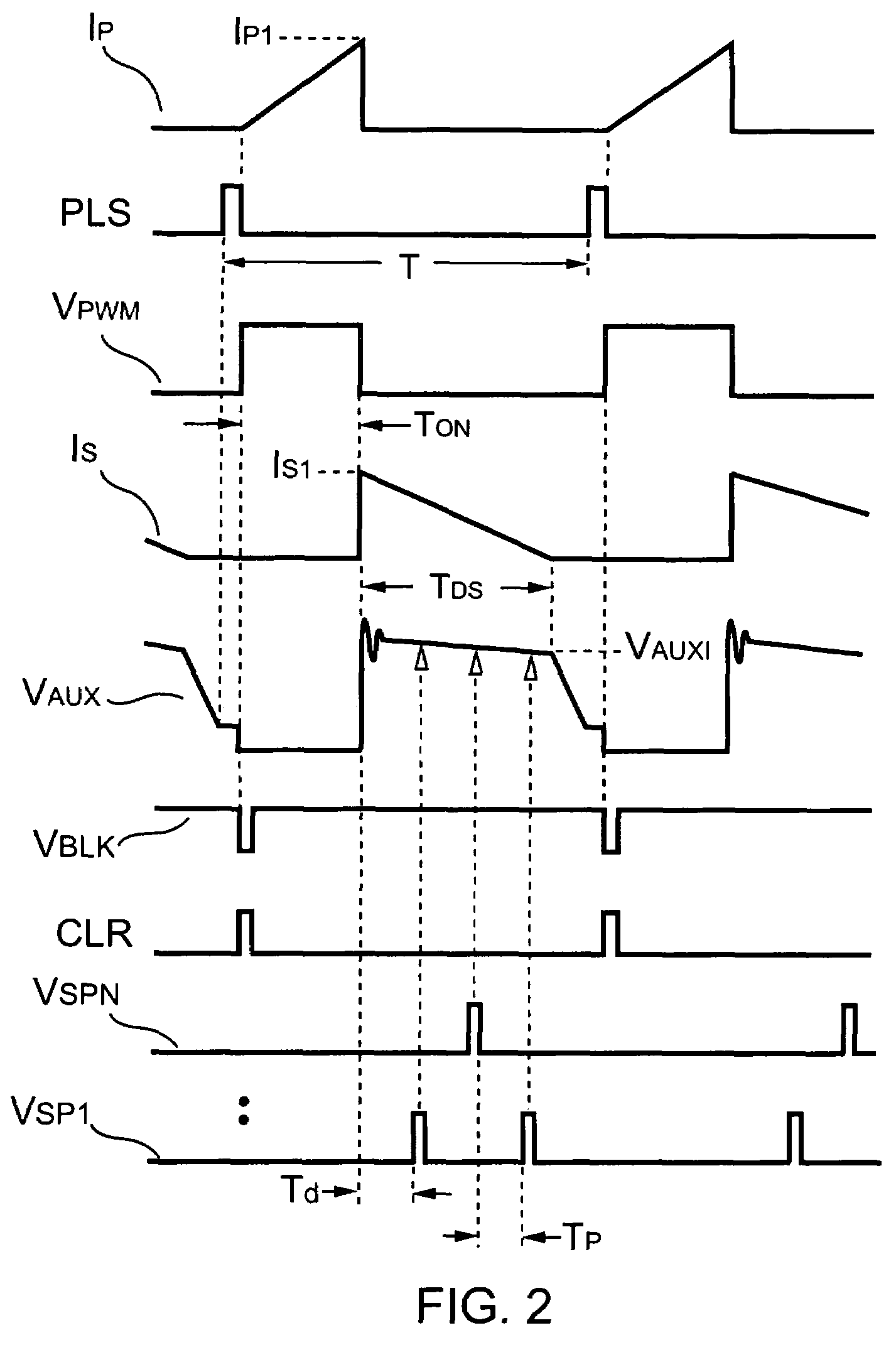
[0021]FIG. 2 illustrates a plurality of signal waveforms of the conventional switching regulator illustrated in FIG. 1. As the switching signal VPWM is a logic-high, a primary-side switching current IP shall be generated accordingly. A peak value IP1 of the primary-side switching current IP is given by:

[0022]IP⁢⁢1=VINLP×TON(1)

where VIN is an input voltage applied to the transformer 10, LP is the inductance of the primary winding NP of the transformer 10, and TON is an on-time of the switching signal VPWM.

[0023]Once the switching signal VPWM is dropped to a logic-low, the energ...


PUM


Abstract

A switching regulator includes a switching device to switch a transformer from a primary-side to secondary side. A control circuit generates a switching signal for regulating output of the switching regulator. The control circuit includes a first circuit to generate a first signal and a timing signal by measuring a reflected signal of the transformer. A second circuit produces a second signal by integrating a current signal with the timing signal. The current signal represents a primary-side switching current of the transformer. A first feedback circuit produces a first feedback signal in response to the first signal and the reference signal, in which the reference signal is varied in response to the change of the second signal. Furthermore, a second feedback circuit generates a second feedback signal in response to the second signal. A switching control circuit generates the switching signal in response to the feedback signals.

Description

BACKGROUND OF THE INVENTION[0001]1. Field of the Invention[0002]The present invention relates to a switching regulator, and more specifically it relates to an isolated switching regulator.[0003]2. Description of Related Art[0004]Various switching regulators have been widely used for providing regulated voltage and current. For safety reasons, off-line switching regulators must provide isolation between their primary side and secondary side. Therefore, a control circuit is equipped at the primary side of a switching regulator, an optical-coupler, and the secondary-side circuit are needed to regulate an output voltage and an output current of the switching regulator. To reduce the size and cost of the switching regulator, the need of optical-coupler and secondary-side circuit to be eliminated is the trend.[0005]In recent developments, many primary side control schemes have been disclosed such as U.S. Pat. No. 6,721,192 entitled “PWM controller regulating output voltage and output curr...

Claims


Application Information

Patent Timeline
Patent Type & Authority Patents(United States)
IPC IPC(8): H02M3/335
CPCH02M3/33523
Inventor YANG, TA-YUNGLI, CHUH-CHINGTSAO, FENG CHENG
Owner FAIRCHILD SEMICON CORP
Why Eureka
Try Eureka