Optimized switching configurations for reconfigurable arrays of sensor elements

a sensor array and reconfigurable technology, applied in the field of reconfigurable arrays of sensors, can solve the problems of not being able to create larger cells that still perform well, switching or multiplexing has been used in several cases for much more limited reconfigurability, and little if any work has gone into algorithms for improving the performance of switching networks. , to achieve the effect of minimizing a cost function

Inactive Publication Date: 2008-04-01
GENERAL ELECTRIC CO
View PDF43 Cites 38 Cited by
  • Summary
  • Abstract
  • Description
  • Claims
  • Application Information

AI Technical Summary

Benefits of technology

[0018]A further aspect of the invention is a method for operating an ultrasound imaging system having an array of ultrasonic transducer elements that are reconfigurable by controlling the respective states of a network of switches, comprising the following steps: (a) optimizing a first switching configuration for use in a first operating state of the ultrasound imaging system; and (b) optimizing a second switching configuration for use in a second operating state of the ultrasound imaging system, wherein the optimizing steps involve minimizing a cost function using an iterative algorithm.
[0019]Yet another aspect of the invention is a method for operating an ultrasound imaging system having an array of ultrasonic transducer elements that are reconfigurable by controlling the respective states of a network of switches, comprising the following steps: (a) optimizing a first switching configuration for use in a first operating state of the ultrasound imaging system by minimizing a first cost function using a first iterative algorithm; and (b) optimizing a second switching configuration for use in a second operating state of the ultrasound imaging system by minimizing a second cost function using a second iterative algorithm, the second cost function being different than said first cost function.

Problems solved by technology

Little if any work has gone into algorithms for improving the performance of the switching networks required for beamforming.
However, switching or multiplexing has been used in several cases for much more limited reconfigurability.
It may not be possible to create larger cells that still perform well in terms of frequency response and sensitivity desired.
Unfortunately, it is difficult to produce electronics that would allow individual control over such small cells.
While in terms of the acoustical performance of the array as a whole, the small cell size is excellent and leads to great flexibility, control is limited to larger structures.
However, subelements comprise connected cells that are not switchably disconnectable and thus cannot be reconfigured.
Reconfigurable ultrasound arrays require a complex switching network that may be difficult or impossible to implement with currently available electronics.

Method used


Image

  • Optimized switching configurations for reconfigurable arrays of sensor elements
  • Optimized switching configurations for reconfigurable arrays of sensor elements
  • Optimized switching configurations for reconfigurable arrays of sensor elements

Examples


Embodiment Construction

[0051]The invention is directed to a reconfigurable switching matrix and a method for optimizing switching configurations for such a matrix and its associated array of sensor elements. For the purposes of illustration, the reconfigurable array and the optimization method will be described with reference to capacitive micromachined ultrasonic transducers (cMUTs). However, it should be understood that the aspects of the invention disclosed herein are not limited in their application to probes employing cMUTs, but rather may also be applied to probes that employ pMUTs or even diced piezoceramic arrays where each of the diced subelements are connected by interconnect means to an underlying switching layer. The same aspects of the invention also have application in reconfigurable arrays of optical, thermal or pressure sensors.

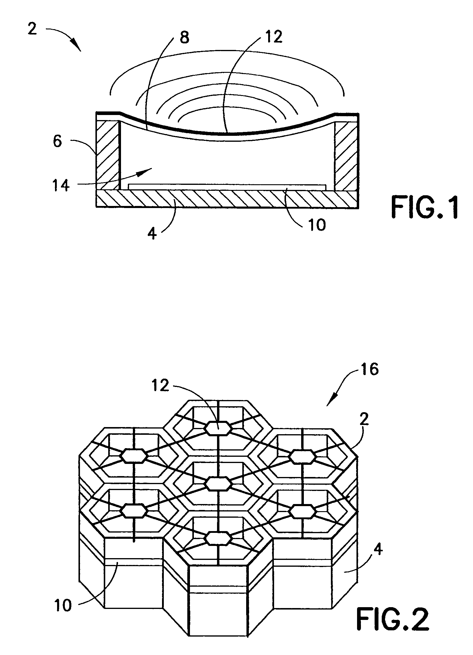
[0052]Referring to FIG. 1, a typical cMUT transducer cell 2 is shown in cross section. An array of such cMUT transducer cells is typically fabricated on a substrate...


PUM


Abstract

The reconfigurable ultrasound array disclosed herein is one that allows groups of subelements to be connected together dynamically so that the shape of the resulting element can be made to match the shape of the wave front. This can lead to improved performance and / or reduced channel count. Reconfigurability can be achieved using a switching network. A methodology and an algorithm are disclosed that allows the performance of this switching network to be improved by properly choosing the configuration of the switching network.

Description

RELATED PATENT APPLICATION[0001]This application is a continuation-in-part of and claims priority from U.S. patent application Ser. No. 10 / 383,990 filed on Mar. 6, 2003 now U.S. Pat. No. 6,865,140 and entitled “Mosaic Arrays Using Micromachined Ultrasound Transducers”.STATEMENT REGARDING FEDERALLY SPONSORED RESEARCH AND DEVELOPMENT[0002]The United States Government may have certain rights in this invention pursuant to U.S. Government Contract Number DAMD17-02-1-0181 awarded by the U.S. Army.BACKGROUND OF THE INVENTION[0003]This invention generally relates to reconfigurable arrays of sensors (e.g., optical, thermal, pressure, ultrasonic). In particular, the invention relates to reconfigurable micromachined ultrasonic transducer (MUT) arrays. One specific application for MUTs is in medical diagnostic ultrasound imaging systems. Another specific example is for non-destructive evaluation (NDE) of materials, such as castings, forgings, or pipelines.[0004]Conventional ultrasound imaging s...

Claims


Application Information

Patent Timeline
Patent Type & Authority Patents(United States)
IPC IPC(8): A61B5/05A61B8/00B06B1/02B06B1/06H04R17/00
CPCB06B1/0292G10K11/34G01S15/8925A61B2562/028G01S7/52046B06B1/06G06T7/00
Inventor HAZARD, CHRISTOPHER ROBERTWODNICKI, ROBERT GIDEONFISHER, RAYETTE ANNTHOMENIUS, KAI E.SMITH, LOWELL SCOTTMILLS, DAVID MARTIN
Owner GENERAL ELECTRIC CO
Why Eureka
Try Eureka