Can opener

a can opener and operable technology, applied can solve the problems of inability to operate or survive, and the operation is not reliable, and the can openers cannot be used in the field of manually operable can openers

Inactive Publication Date: 2008-04-08
KI MEE KITCHENWARE
View PDF10 Cites 13 Cited by
  • Summary
  • Abstract
  • Description
  • Claims
  • Application Information

AI Technical Summary

Benefits of technology

[0011]It is advantageous that the ratchet assembly is positioned between the operating member and the traction wheel in a direction parallel to the operating axis.

Problems solved by technology

None of these can openers survive for various reasons, probably mainly because that they are not reliable in construction or operation and / or are difficult to use.

Method used


Image

  • Can opener
  • Can opener
  • Can opener

Examples


Embodiment Construction

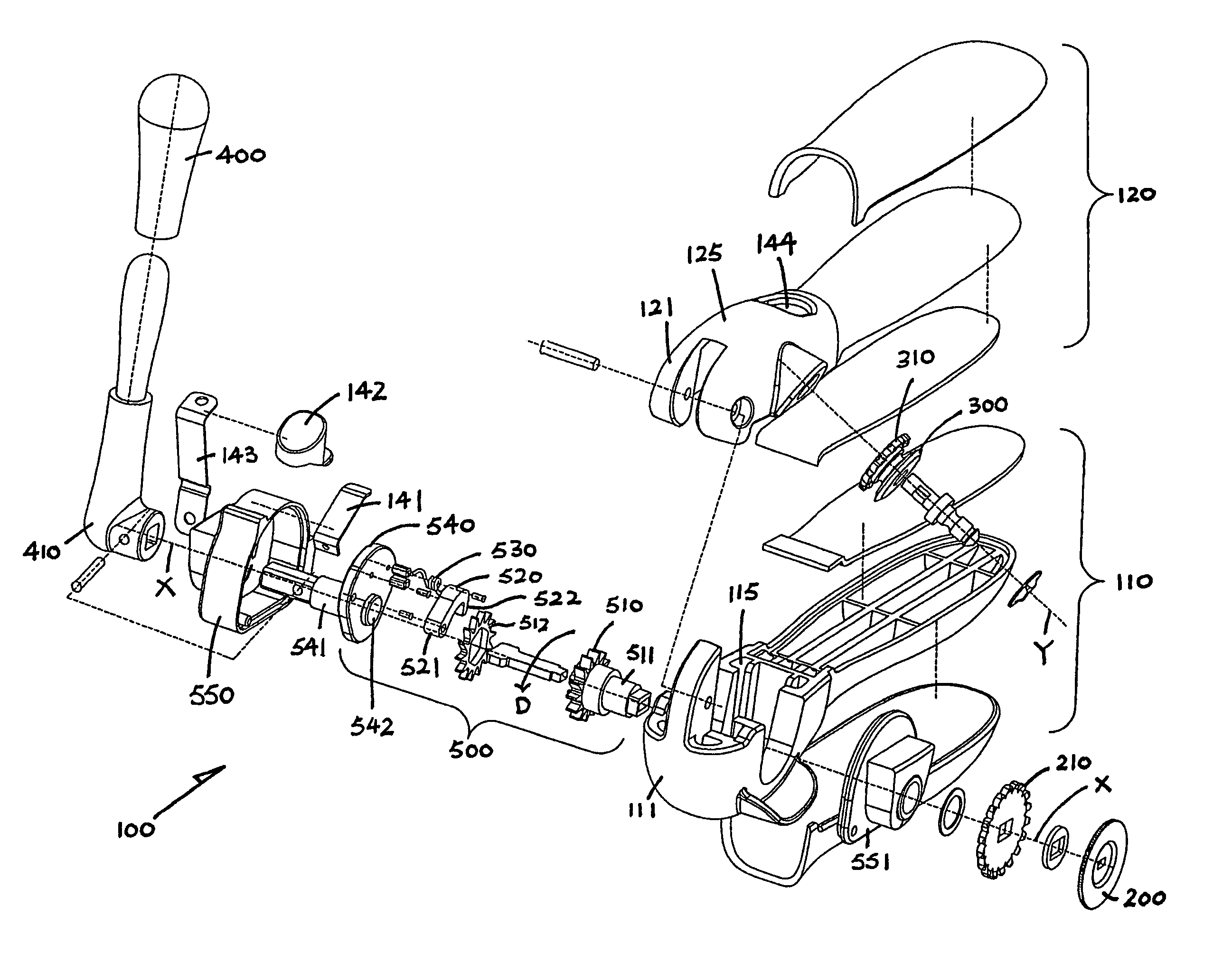
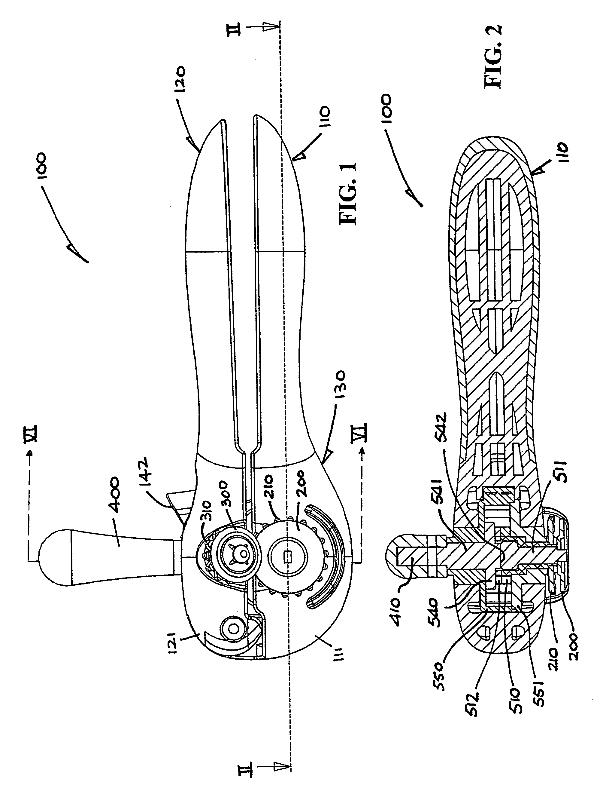
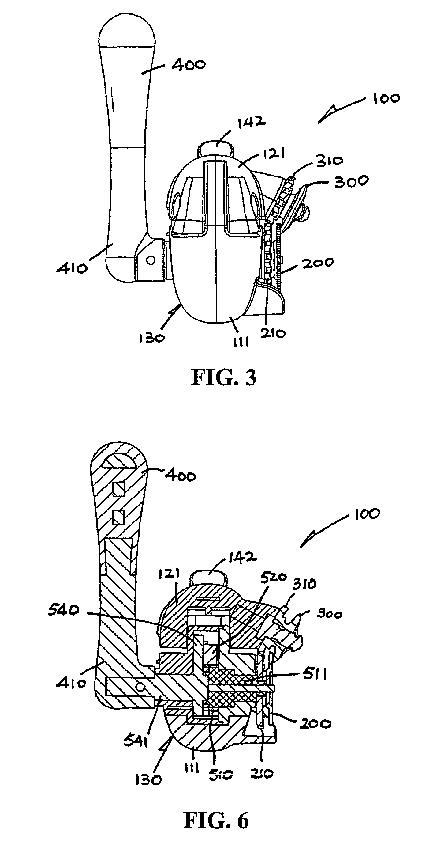
[0026]Referring to the drawings, there is shown a can opener 100 as an exemplary embodiment of the invention, which comprises a pair of bottom and top elongate handle members 110 and 120 hinged together at their frontmost ends 111 and 121 for pivotal movement with respect to each other, and a rotatable traction wheel 200 and a rotatable cutter blade 300 mounted behind the frontmost ends 111 and 121 of the bottom and top handle members 110 and 120 respectively for movement thereby. The wheel 200 and the blade 300 are movable between an inoperative position in which the wheel 200 and the blade 300 are spaced apart for receiving an edge of a can to be opened and an operative position in which the wheel 200 and the blade 300 are close together for turning and cutting the edge of the can.

[0027]Both handle members 110 and 120 are made sufficiently broad and to have an oval cross-section jointly for easy and comfortable gripping by a user. Their front end portions 115 and 125 together expa...


PUM


Abstract

A can opener (100) has two pivotal handles (110 and 120), a traction wheel (200) and a cutter blade (300) movable by respective handles (110 and 120) for cutting open a can, and a pivotable lever (400). There is a ratchet assembly (500) driven by the lever (400) upon reciprocation for operating the traction wheel (200) and cutter blade (300), which has a ratchet wheel (510) connected with the traction wheel (200) and a spring-loaded pawl (520) movable by the lever (400) for turning the ratchet wheel (510) in a driving direction (D) upon reciprocation of the lever (400). The pawl (520) has front and rear ends (521 and 522) taken in the driving direction (D), with the front end (521) in engagement with the lever (400) and the rear end (522) engageable with the ratchet wheel (510) for turning the same.

Description

PRIORITY CLAIM[0001]This application claims the benefit of prior United Kingdom Application Ser. No. 421717.0 filed Sep. 30, 2004.FIELD OF THE INVENTION[0002]The invention relates to a manually operable can opener.BACKGROUND OF THE INVENTION[0003]Can openers have been known for many years, and the typical construction includes a traction wheel for turning a can and a disc-like cutter blade for rotation while the can is being turned to cut open the can. Conventionally, the traction wheel is turned by means of an operating member mostly in the form of a wing knob. Can openers that can be operated by pivoting a lever or the like are not new, for example as disclosed in published patent specifications GB 613,146, U.S. Pat. No. 5,970,618, WO 03 / 043,929 A1 and US 2002 / 0088127 A1. None of these can openers survive for various reasons, probably mainly because that they are not reliable in construction or operation and / or are difficult to use.[0004]The invention seeks to obviate or at least ...

Claims


Application Information

Patent Timeline
Patent Type & Authority Patents(United States)
IPC IPC(8): B67B7/72B67B7/46B67B7/70
CPCB67B7/32B67B7/34
Inventor SO
Owner KI MEE KITCHENWARE
Why Eureka
Try Eureka