Travelator, moving ramp or escalator

a technology of moving ramps and escalators, which is applied in the direction of escalators, conveyors, transportation and packaging, etc., can solve the problems of long transport distances, high cost, and high cost of drive elements, and achieves low cost, low cost, and long transport lengths.

Active Publication Date: 2008-04-08
KONE CORP
View PDF8 Cites 25 Cited by
  • Summary
  • Abstract
  • Description
  • Claims
  • Application Information

AI Technical Summary

Benefits of technology

[0011]Another object of the invention is to provide a travelator, moving ramp or escalator in which it is possible to use longer and thinner, inexpensive drive elements requiring a lower tolerance accuracy than before.
[0012]A further object of the invention is to provide a travelator, moving ramp or escalator in which unequal wear of the drive elements causes less problems than before.
[0013]A further object of the invention is to provide a travelator, moving ramp or escalator in which the load is better distributed between the drive elements.
[0014]Yet another object of the invention is to provide a travelator, moving ramp or escalator in which the transport platforms are prevented from getting into an oblique position relative to the transport direction at the non-driven end of the conveyor.
[0016]The invention has the advantage that the second synchronizing device equalizes the error arising from unequal elongation of the drive elements or from other errors between the two drive elements so that the load is evenly distributed on both. This makes it possible to use thinner and more stretchable drive elements than before, which can be manufactured to less strict tolerances than before. Furthermore, the invention makes it possible to produce a longer travelator, moving ramp or escalator designed to be mounted on a fixed base than before.

Problems solved by technology

In conventional prior-art travelators, moving ramps and escalators, the transport length of the conveyor is reasonably short and the link chains usually employed as drive elements are of a very heavy design.
Today, however, there is a need for travelators, moving ramps and / or escalators in which the transport distances are very long and in which the distance between the driving and diverting pulleys of the drive elements are consequently also very long.
In the frame structure of a travelator, moving ramp or escalator mounted on a fixed base there is very little space for the drive machine of the conveyor, and therefore the diameter of the driving and diverting pulleys can not be very large and correspondingly the drive elements used, such as link chains or belts, are also quite thin, so their elongations and accordingly the difference of elongation may become large enough to cause problems.
Uneven loading again may be due to the fact that passengers usually stand on the right-hand side of the conveyor.
In prior art, as the diverting pulleys at the non-driven end of the conveyor are in no way synchronized with each other and because the transport platforms are fastened to both drive elements, the difference of elongation accumulating at the non-driven end of the conveyor leads to a problematic situation where the transport platforms especially near the non-driven end of the conveyor tend to move in a position differing from the mutually parallel position at the driven end, that is to say, in an oblique position relative to the transport direction, which may result in the transport platforms being stuck on their guide rails, thus stopping the conveyor.

Method used


Image

  • Travelator, moving ramp or escalator
  • Travelator, moving ramp or escalator
  • Travelator, moving ramp or escalator

Examples


Embodiment Construction

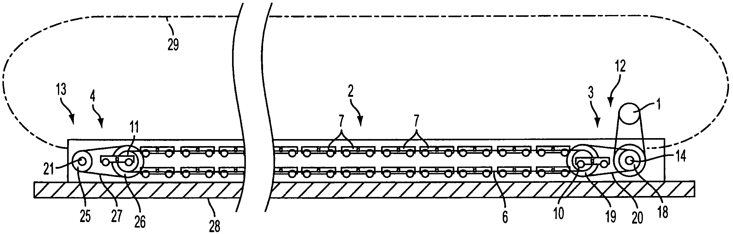
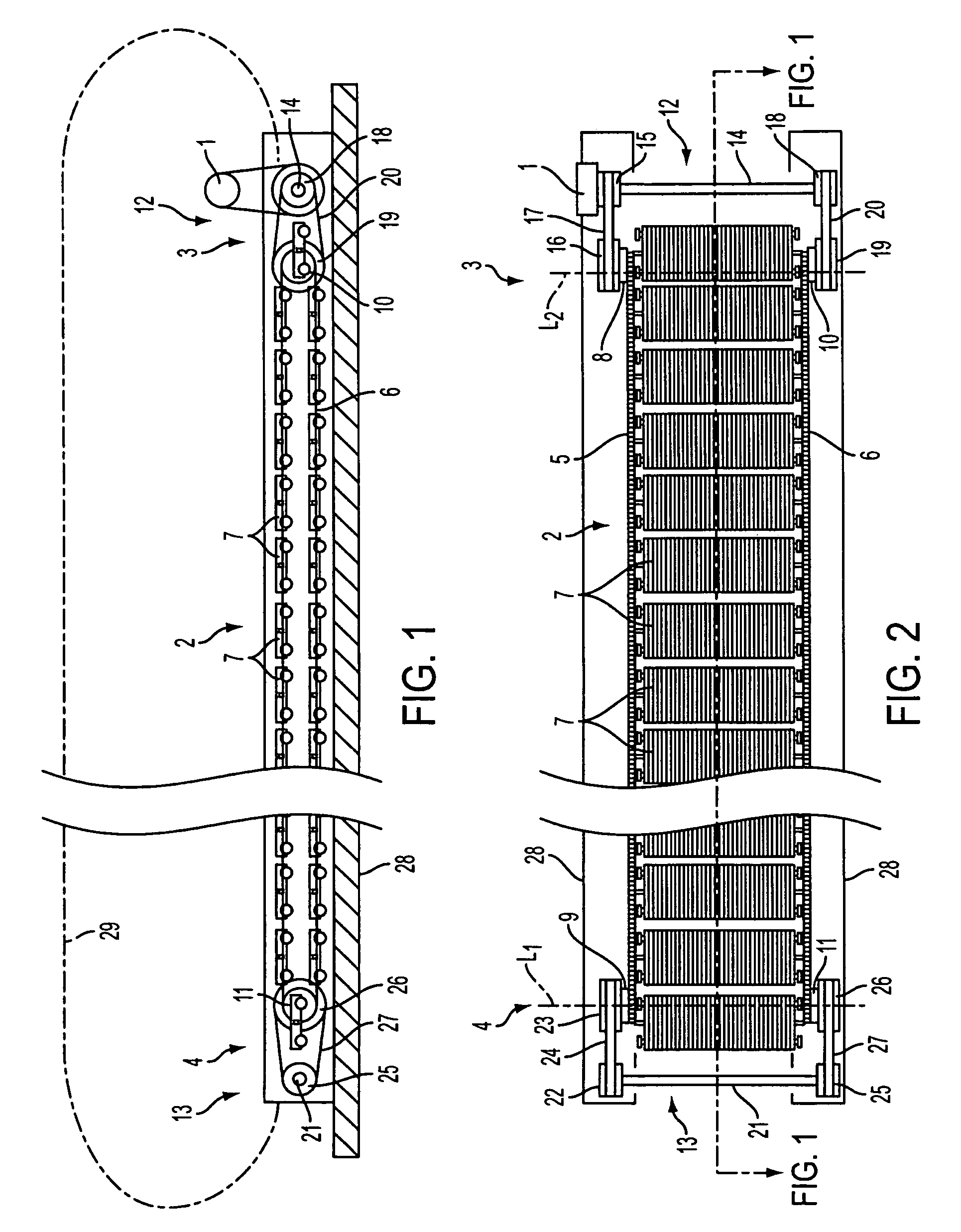
[0024]FIGS. 1 and 2 illustrate a horizontal travelator having a low-construction height mounted on a fixed base, such as a floor or other support, which means that no pit needs to be made in the fixed base for the travelator machinery. A travelator having a low construction height is described, for example, in co-owned U.S. application Ser. No. 11 / 491,495, filed Jul. 24, 2006, the disclosure of which is incorporated herein by reference. In the following description of an example, the invention is described in connection with a travelator, but it is obvious that corresponding principles of the invention can be applied to moving ramps and escalators as well.

[0025]The illustrated travelator comprises a conveyor 2, which in this case is a pallet conveyor. The conveyor 2 is mounted on a conveyor frame 28. The conveyor frame 28 lies on a floor base throughout its length. Secured to the conveyor frame 28 are usually two balustrades 29 extending alongside the conveyor 2 throughout its lengt...


PUM


Abstract

A travelator, moving ramp or escalator comprises a conveyor having a driven end driven by a power machine and a non-driven end. At the driven end, a first drive element, in the form of an endless loop, is passed over a first driving pulley rotated by the power machine, and at the non-driven end the first drive element is passed over a first diverting pulley. A second drive element, in the form of an endless loop, is passed over a second driving pulley at the driven end rotated by the power machine, and over a second diverting pulley at the non-driven end. A first synchronizing device at the driven end provides mutual synchronization of the first and second driving pulleys. The conveyor additionally comprises a second synchronizing device arranged at the non-driven end for mutual synchronization of the first and second diverting pulleys.

Description

CROSS-REFERENCE TO RELATED APPLICATIONS[0001]This application is a continuation of International Application No. PCT / FI2005 / 00049, filed Jan. 26, 2005, designating the United States and claiming priority from Application FI20040303 filed in Finland on Feb. 26, 2004. The disclosures of both foregoing applications is incorporated herein by reference.BACKGROUND OF THE INVENTION[0002]The present invention relates to a travelator, moving ramp or escalator. In prior art, a travelator, moving ramp or escalator is known which comprises a power means and a conveyor having an end driven by the power means and a non-driven end. The conveyor comprises a first drive element and a second drive element, which are disposed at a distance from each other and parallel to each other, each being implemented as an endless loop. The drive elements are usually link chains or toothed belts.[0003]A number of conveyor platforms, such as pallets, are arranged one after the other and secured to the first and th...

Claims


Application Information

Patent Timeline
Patent Type & Authority Patents(United States)
IPC IPC(8): B65G21/00B66B21/00
CPCB66B21/00B66B23/026B66B21/10
Inventor AULANKO, ESKOMUSTALAHTI, JORMAOSSENDORF, MARC
Owner KONE CORP
Why Eureka
Try Eureka