
Inkjet recording apparatus

a recording apparatus and inkjet technology, applied in printing and other directions, can solve the problems of contaminated conveying units, large space in which the cover is disposed, and large apparatus, and achieve the effects of miniaturizing the apparatus, reducing the space for storing the reception member, and miniaturizing the inkjet recording apparatus

Inactive Publication Date: 2008-04-08
BROTHER KOGYO KK
View PDF14 Cites 7 Cited by
  • Summary
  • Abstract
  • Description
  • Claims
  • Application Information

AI Technical Summary

Benefits of technology

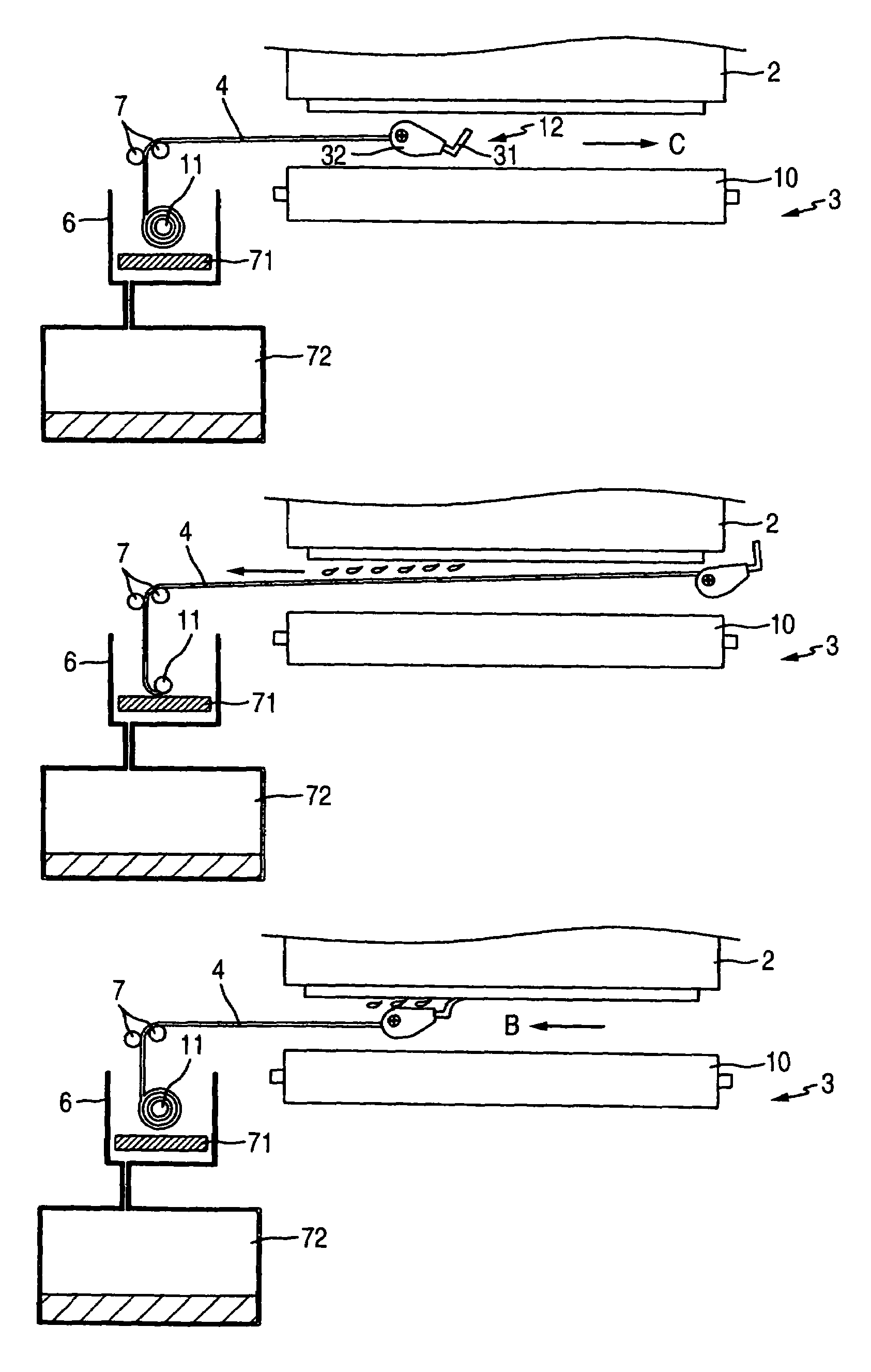
The invention is an inkjet recording apparatus that prevents ink from spilling during a purge process and prevents the ink from contaminating the conveyance unit or recording medium. The apparatus includes a recording head, a recovery unit, a reception member, and an arrangement mechanism. The recording head ejects ink for recording, and the recovery unit causes the recording head to perform a purge process. The reception member receives the ink ejected in the purge process and is stored compactly outside the recording area to prevent disturbs the conveyance of the recording medium. The arrangement mechanism pulls out the reception member when the recovery unit causes the recording head to perform the purge process. The technical effect of the invention is to miniaturize the inkjet recording apparatus.

Problems solved by technology

However, since a larger amount of ink than that in the flushing process is discharged in the purge process, it is likely that the conveyance unit is contaminated with the ink spilling from the opening portion of the cover.
In addition, when the cover having no opening portion is moved forward and backward or when the recording head is covered with the cover formed into a cylindrical shape or the like, there is a problem that the space in which the cover is disposed becomes so large that the apparatus becomes large in size.

Method used


Image

  • Inkjet recording apparatus
  • Inkjet recording apparatus
  • Inkjet recording apparatus

Examples


Embodiment Construction

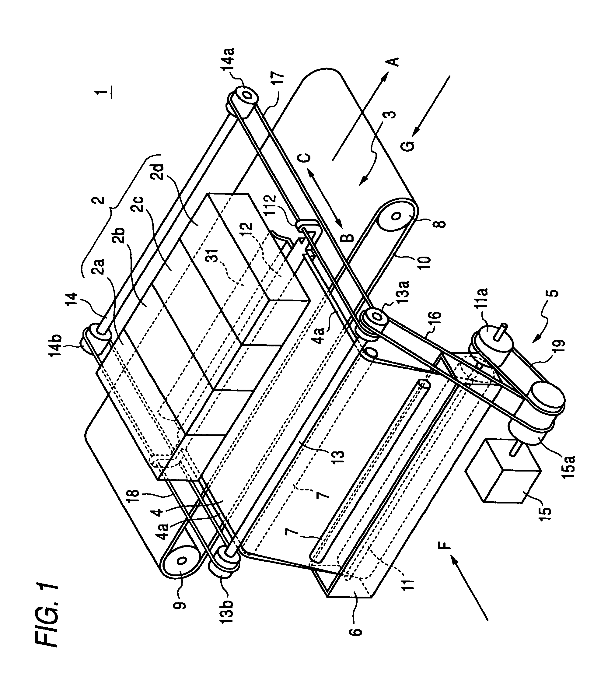
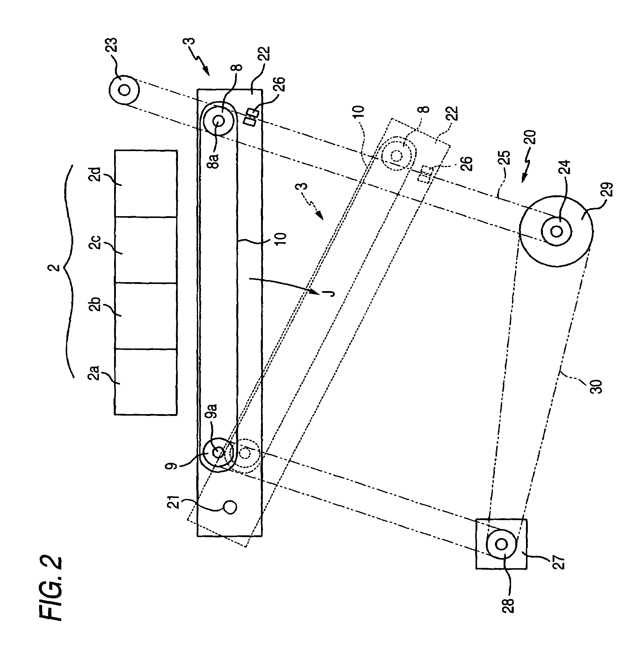
[0019]A preferred embodiment of the invention will be described below with reference to the accompanying drawings. FIG. 1 is a perspective view schematically showing an inkjet recording apparatus 1 according to the embodiment of the invention. In the inkjet recording apparatus 1, ink is ejected from nozzles formed in a recording head 2 so as to perform recording on a recording medium. In this embodiment, description will be made particularly on a so-called line-type inkjet recording apparatus 1 in which nozzles are formed in a long recording head 2 so as to extend across a recording area of a recording medium, and the recording medium is conveyed onto a surface opposed to a nozzle formation surface of the recording head 2 while the recording head 2 is fixed, so that recording is performed at one stroke.

[0020]The inkjet recording apparatus 1 chiefly includes a line-type recording head 2, a conveyance unit 3 disposed at a position opposed to the recording head 2, an ink reception shee...


PUM


Abstract

An inkjet recording apparatus includes a recording head, a recovery unit, a reception member, and an arrangement mechanism. The recording head ejects ink therefrom to perform recording on a recording medium. The recovery unit causes the recording head to perform a purge process. The reception member receives the ink ejected in the purge process and has flexibility. The arrangement mechanism stores the reception member, which is in a wound state, outside a recoding area where the recording head performs the recording on the recording medium. The arrangement mechanism pulls out the reception member when the recovery unit causes the recording head to perform the purge process.

Description

BACKGROUND OF THE INVENTION[0001]1. Field of the Invention[0002]The present invention relates to an inkjet recording apparatus, and particularly relates to an inkjet recording apparatus in which ink ejected in a purge process can be received without contaminating a conveyance unit or a recording medium and in which a reception member for receiving the ink can be stored compactly so that the apparatus can be miniaturized.[0003]2. Description of the Related Art[0004]So-called line type inkjet recording apparatus is known as an inkjet recording apparatus for ejecting ink from nozzles of a recording head to thereby perform recording on a recording medium. In the line type inkjet recording apparatus, nozzles are formed in a long recording head so as to extend across a recording area of a recording medium. The recording medium is conveyed onto a surface opposed to a nozzle formation surface of the recording head while the recording head is fixed. Thus, recording is performed at one stroke...

Claims


Application Information

Patent Timeline
Patent Type & Authority Patents(United States)
IPC IPC(8): B41J2/165B41J2/18B41J2/185
CPCB41J2/16523B41J2/16585B41J2/16526B41J2002/1742B41J2/1742
Inventor OKAMOTO, TSUGIO
Owner BROTHER KOGYO KK
Learn More