

Evaporating apparatus
a technology of evaporating head and evaporating chamber, which is applied in the direction of mechanical equipment, vacuum evaporation coating, spindle sealing, etc., can solve the problems of affecting reducing the efficiency of evaporation head, so as to reduce the cost of evaporation or running cost, the effect of reducing the vapor deposition ra
- Summary
- Abstract
- Description
- Claims
- Application Information
AI Technical Summary
Benefits of technology
Problems solved by technology
Method used
Image

Examples
Embodiment Construction
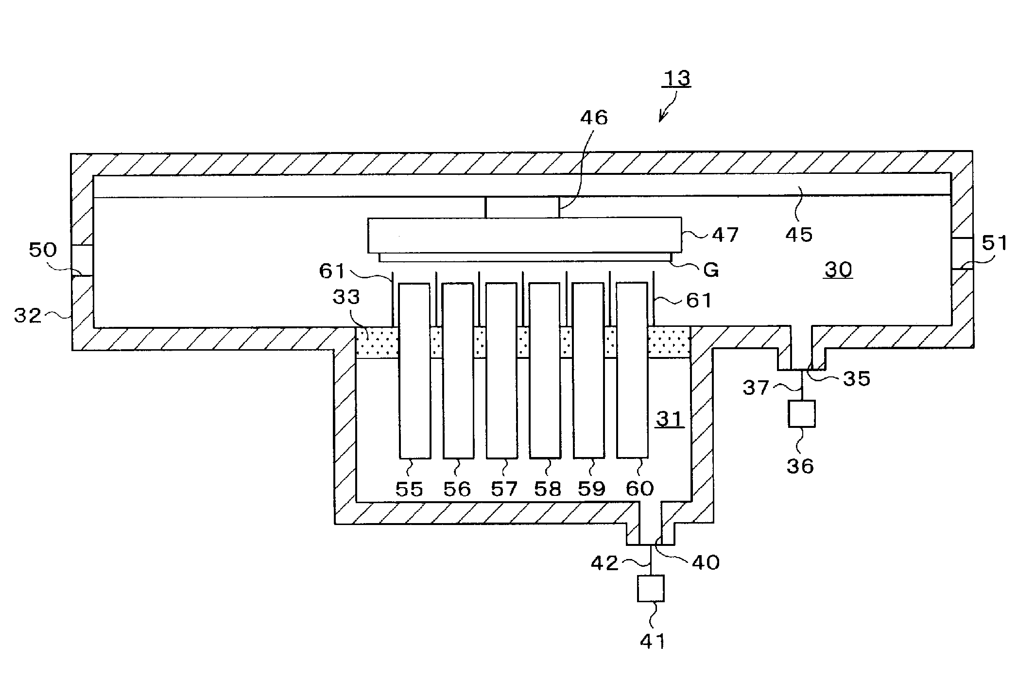
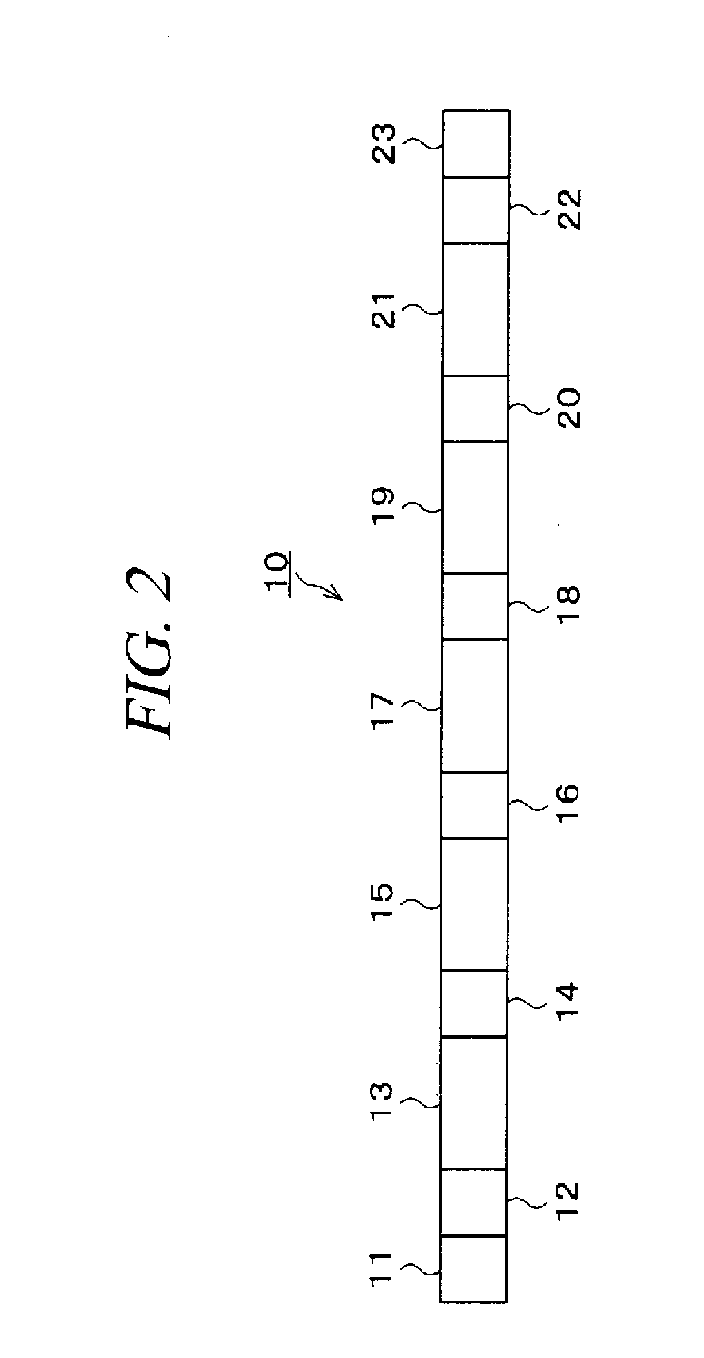
[0055]Hereinafter, an embodiment of the present invention will be described in detail with reference to the accompanying drawings. In the following embodiment, a processing system 10 for manufacturing an organic EL device A by forming an anode (positive electrode) layer 1, a light emitting layer 3 and a cathode (negative electrode) layer 2 on a glass substrate G as a target object to be processed will be described in detail as an example of a vapor deposition process. Further, like reference numerals denote like parts through the whole document, and redundant description thereof will be omitted.
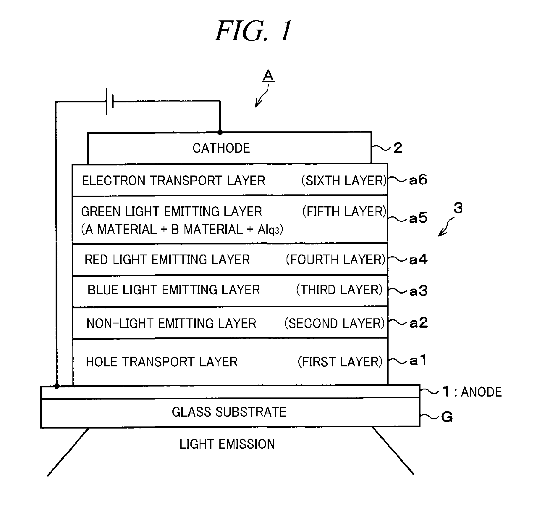
[0056]FIG. 1 provides a diagram for describing the organic EL device A manufactured in accordance with the embodiment of the present invention. The most typical structure of this organic EL device A is a sandwich structure in which the light emitting layer 3 is interposed between the anode 1 and the cathode 2. The anode 1 is formed on the glass substrate G. A transparent electrode made of, e....
PUM
 Abstract
Description
Claims
Application Information