Liquid ejecting apparatus and pressurizing/depressurizing method thereof

a technology of liquid ejecting apparatus and pressurizing/depressurizing method, which is applied in the direction of printing, other printing apparatus, etc., can solve the problems of deteriorating printing quality, ejecting liquid not appropriately, and deteriorating printing quality

Active Publication Date: 2015-03-26
SEIKO EPSON CORP
View PDF9 Cites 4 Cited by
  • Summary
  • Abstract
  • Description
  • Claims
  • Application Information

AI Technical Summary

Benefits of technology

[0011]Here, it is possible to miniaturize the apparatus by performing a depressurizing / pressure accumulating process and a pressurizing / pressure accumulating process using the same pump, and to suppress a cost of the apparatus.
[0015]In the pressurizing / depressurizing method, the depressurizing / pressure accumulating and the pressurizing / pressure accumulating may be selectively performed, and the depressurizing / pressure accumulating and the pressurizing / pressure accumulating may be performed in parallel by switching the first switching unit to the depressurization position, and switching the second switching unit to the pressurization position. When performing the processes in parallel in this manner, it is possible to reduce a total time which is necessary when performing pressurizing / pressure accumulating with respect to the pressurization buffer tank and depressurizing / pressure accumulating with respect to the depressurization buffer tank.
[0016]In the pressurizing / depressurizing method, excessive depressurizing inside the depressurization buffer tank may be prevented by stopping the depressurizing / pressure accumulating when the inside of the depressurization buffer tank is depressurized so as to be a first pressure value. In addition, it is possible to minimize a time necessary until a negative pressure is accumulated in the depressurization buffer tank, and to efficiently perform the depressurizing / pressure accumulating process.
[0017]In the pressurizing / depressurizing method, the excessive pressurizing inside the pressurization buffer tank may be prevented by stopping the pressurizing / pressure accumulating when the inside of the pressurization buffer tank is pressurized so as to be a second pressure value which is high. In addition, it is possible to minimize a time necessary until a positive pressure is accumulated in the pressurization buffer tank, and to efficiently perform the pressurizing / pressure accumulating process.

Problems solved by technology

In such an apparatus, there is a case in which ejecting of liquid is not appropriately performed due to bubbles in liquid, and for example, a quality of printing using liquid deteriorates.
In addition, since it is not possible to perform good liquid ejection when bubbles or foreign substances are mixed into nozzles, for example, a printing quality deteriorates.
However, a value of a positive pressure or a negative pressure which is applied from the pump is unstable immediately after starting the operation of the pump.
In addition, there is a case in which it is difficult to preferably perform pressurizing and depressurizing, when the operation of the pump is limited due to an operational condition of an apparatus, or the like.
In the pressurizing / depressurizing method, when the depressurizing / pressure accumulating is stopped while the pressurizing / pressure accumulating is executed by switching the second switching unit to the pressurization position, there is a possibility that an excessive pressure is applied to the inlet port side of the pump.
In the pressurizing / depressurizing method, when the pressurizing / pressure accumulating process is stopped while the depressurizing / pressure accumulating is executed by switching the first switching unit to the depressurization position, there is a possibility that an excessive pressure is applied to the outlet port side of the pump, however, the applying of pressure may be relieved by performing an atmosphere release by switching the second switching unit to the pressurization stop position.

Method used


Image

  • Liquid ejecting apparatus and pressurizing/depressurizing method thereof
  • Liquid ejecting apparatus and pressurizing/depressurizing method thereof
  • Liquid ejecting apparatus and pressurizing/depressurizing method thereof

Examples


first embodiment

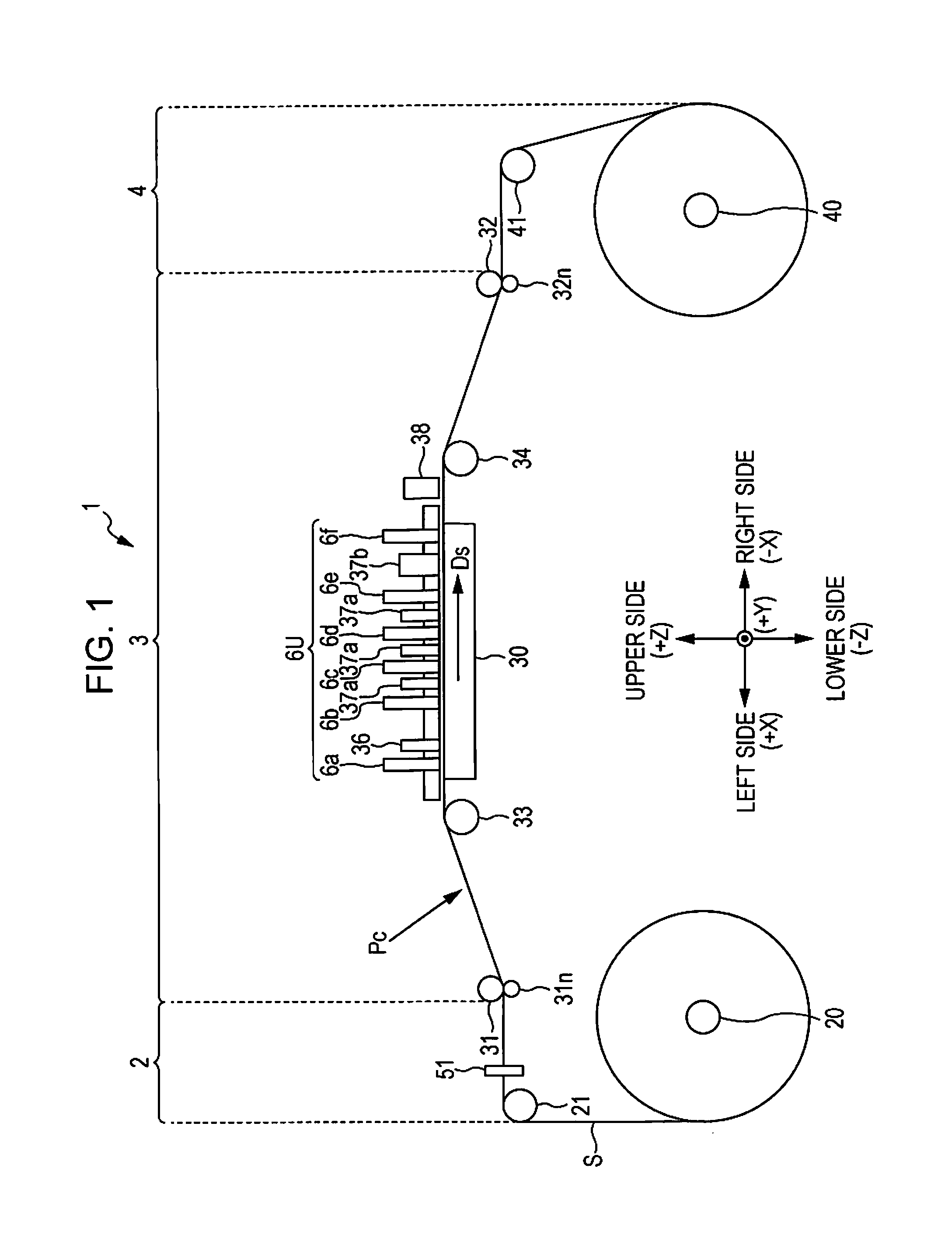
[0030]FIG. 1 is a front view which schematically illustrates a configuration of a printer according to a first embodiment of a liquid ejecting apparatus of the present invention. In addition, in FIG. 1, or in the following figures, a three-dimensional coordinate system corresponding to a horizontal direction X, a front / rear direction Y, and a vertical direction Z of the printer 1 is adopted as necessary in order to make a relation in arrangement of each unit of the printer 1 clear.

[0031]As illustrated in FIG. 1, a feeding unit 2, a process unit 3, and a winding unit 4 are arranged in the horizontal direction in the printer 1. The feeding unit 2 and the winding unit 4 include a feeding axis 20 and a winding axis 40, respectively. In addition, both ends of a sheet S (medium) are wound around in a roll shape around the feeding unit 2 and the winding unit 4, and are stretched therebetween. In this manner, the sheet S is transported to the process unit 3 from the feeding axis 20 along a ...

second embodiment

[0079]According to the first embodiment, the pressurizing cleaning process is performed as the “pressurizing process” of the invention, however, the “pressurizing process” of the invention is not limited to this. Hereinafter, this point will be described based on a second embodiment.

[0080]FIG. 8 is a diagram which illustrates a configuration of a printer which is the second embodiment of the liquid ejecting apparatus according to the invention. In addition, FIGS. 9A and 9B are diagrams which illustrate a configuration of an ink reservoir. A big difference in the second embodiment from the first embodiment is that a configuration of pressurizing the ink reservoir 671 in the pressure adjusting mechanism 68 is added, and configurations other than that are the same as those of the first embodiment.

[0081]The ink reservoir 671 is provided as an ink pack 6711 as illustrated in FIG. 9A, for example. The ink pack 6711 is accommodated in a housing 6712 in a state of being interposed between t...

third embodiment

[0084]According to the first embodiment, the deaeration process using the deaeration section 93 is performed as the “depressurizing process” of the invention, however, the “depressurizing process” of the invention is not limited to this. Hereinafter, this point will be described based on a third embodiment.

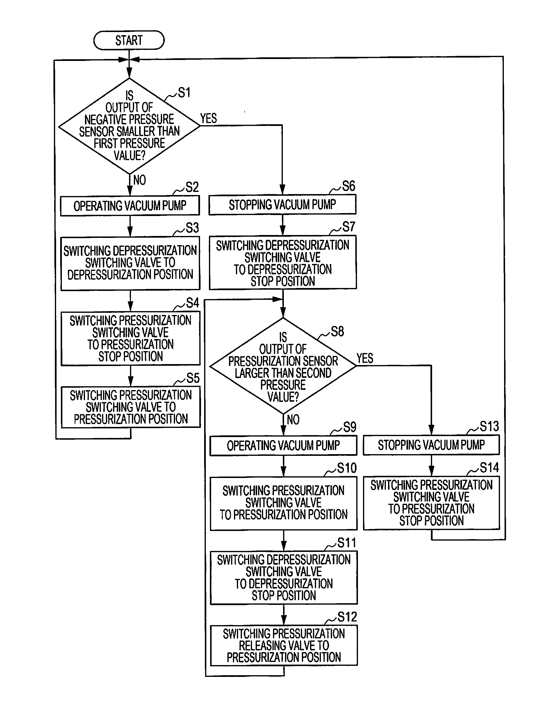
[0085]FIG. 10 is a diagram which illustrates a configuration of a printer which is the third embodiment of the liquid ejecting apparatus according to the invention. A big difference in the third embodiment from the first embodiment is that the three way valve 86 also functions as a depressurization control valve, not only a pressurization releasing valve. More specifically, a point that a port which is used as the atmosphere opening port among ports of the three way valve 86 in the first embodiment is connected to the depressurization buffer tank 71 through the depressurization path 87, and operations of the three way valve 86 are different from those of the first embodiment, and ...


PUM


Abstract

A pressurizing / depressurizing method of a liquid ejecting apparatus which includes a print head which ejects liquid, and a supply unit which supplies the liquid to the print head, the method including depressurizing / pressure accumulating in which a depressurization buffer tank is depressurized, and a pressure is accumulated; pressurizing / pressure accumulating in which a pressurization buffer tank is pressurized, and a pressure is accumulated; depressurizing in which the liquid is depressurized so that a pressure is lower than an atmospheric pressure in the supply unit using the depressurization buffer tank; and pressurizing in which the liquid is pressurized so that the pressure is higher than the atmospheric pressure in the supply unit using the pressurization buffer tank.

Description

BACKGROUND[0001]1. Technical Field[0002]The present invention relates to a technology of pressurizing and depressurizing in which a pressurizing process of pressurizing liquid, and a depressurizing process of depressurizing liquid are performed in a liquid ejecting apparatus which ejects liquid such as ink from nozzles of a print head.[0003]2. Related Art[0004]In the related art, a liquid ejecting apparatus such as a printer which ejects liquid such as ink from nozzles of a print head has been known. In such an apparatus, there is a case in which ejecting of liquid is not appropriately performed due to bubbles in liquid, and for example, a quality of printing using liquid deteriorates. Therefore, for example, in an apparatus disclosed in JP-A-2010-208186, a depressurizing pump is operated after ending a printing operation, and deaeration processing is executed by pressurizing liquid (depressurizing process).[0005]In addition, since it is not possible to perform good liquid ejection ...

Claims


Application Information

Patent Timeline
Patent Type & Authority Applications(United States)
IPC IPC(8): B41J2/175
CPCB41J2/175B41J2/18B41J29/38B41J2/055B41J2/1652B41J2/16526B41J2/17556B41J2/19
Inventor ANDO, MASAAKI
Owner SEIKO EPSON CORP
Why Eureka
Try Eureka