Charger, image forming apparatus and process cartridge

a technology of image forming apparatus and process cartridge, which is applied in the direction of electrographic process apparatus, corona discharge, instruments, etc., can solve the problems of pollution of charging wire, inability to achieve efficient charging, so as to reduce the diameter shorten the circumference of the photoreceptor drum, and relax space-related restrictions effectively

Inactive Publication Date: 2008-04-08
BROTHER KOGYO KK
View PDF8 Cites 8 Cited by
  • Summary
  • Abstract
  • Description
  • Claims
  • Application Information

AI Technical Summary

Benefits of technology

[0009]However, the decrease of the diameter of the photoreceptor drum results in shortening of its circumference. Therefore, where the charger and the other members are arranged around the photoreceptor in its circumferential direction, the charger is prone to interfere with the other members. A charger is desired having such a structure as not to be prone to interfere with the other members and to be able to relax space-related restrictions effectively even in the case where they are arranged around the photoreceptor.
[0010]On the other hand, chargers are configured so as to supply the photoreceptor with ions generated by corona discharge. In an inefficient structure in which generated ions are not very apt to be supplied to the photoreceptor, the amount of discharge needs to be increased to secure a proper amount of ions supplied to the photoreceptor, which increases the apparatus-side Load. In these circumstances, a charger is desired having such a structure that generated ions are apt to be supplied to the photoreceptor and discharge can be caused efficiently.
[0011]The present invention provides a configuration that allows the photoreceptor to be charged efficiently and in which polluted air is not prone to be supplied from around the fixing member to the charger and hence discharge failures can be suppressed effectively.
[0012]The present invention provides a charger having such a structure as to be able to easily accommodate miniaturization of a photoreceptor and to be able to efficiently supply the photoreceptor with ions generated by discharge.

Problems solved by technology

The conventional technique as disclosed in JP-A-2003-287993 has a problem that ions generated by corona discharge do not tend to flow to the photoreceptor side and efficient charging cannot be attained easily because an air flow is generated in the direction from the photoreceptor to the charger.
On the other hand, if an air flow is generated in the opposite direction, that is, in the direction from the charger to the photoreceptor, polluted air is supplied from around a fixing member to the charger and a charging wire is thereby polluted.
Such pollution of the charging wire is caused by sticking of pollutants such as silica.
More specifically, the air around the fixing member contains large amounts of pollutants such as silica that are scattered from around the fixing member.
When air containing those pollutants flows from the fixing member side to the charger side, they stick to and pollute the charging wire.
When the charging wire is polluted in this manner, the thickness of the wire becomes non-uniform.
Unevenness becomes prone to occur in discharge, which influences the image quality.
However, the decrease of the diameter of the photoreceptor drum results in shortening of its circumference.
Therefore, where the charger and the other members are arranged around the photoreceptor in its circumferential direction, the charger is prone to interfere with the other members.

Method used


Image

  • Charger, image forming apparatus and process cartridge
  • Charger, image forming apparatus and process cartridge
  • Charger, image forming apparatus and process cartridge

Examples


first embodiment

1. Total Configuration

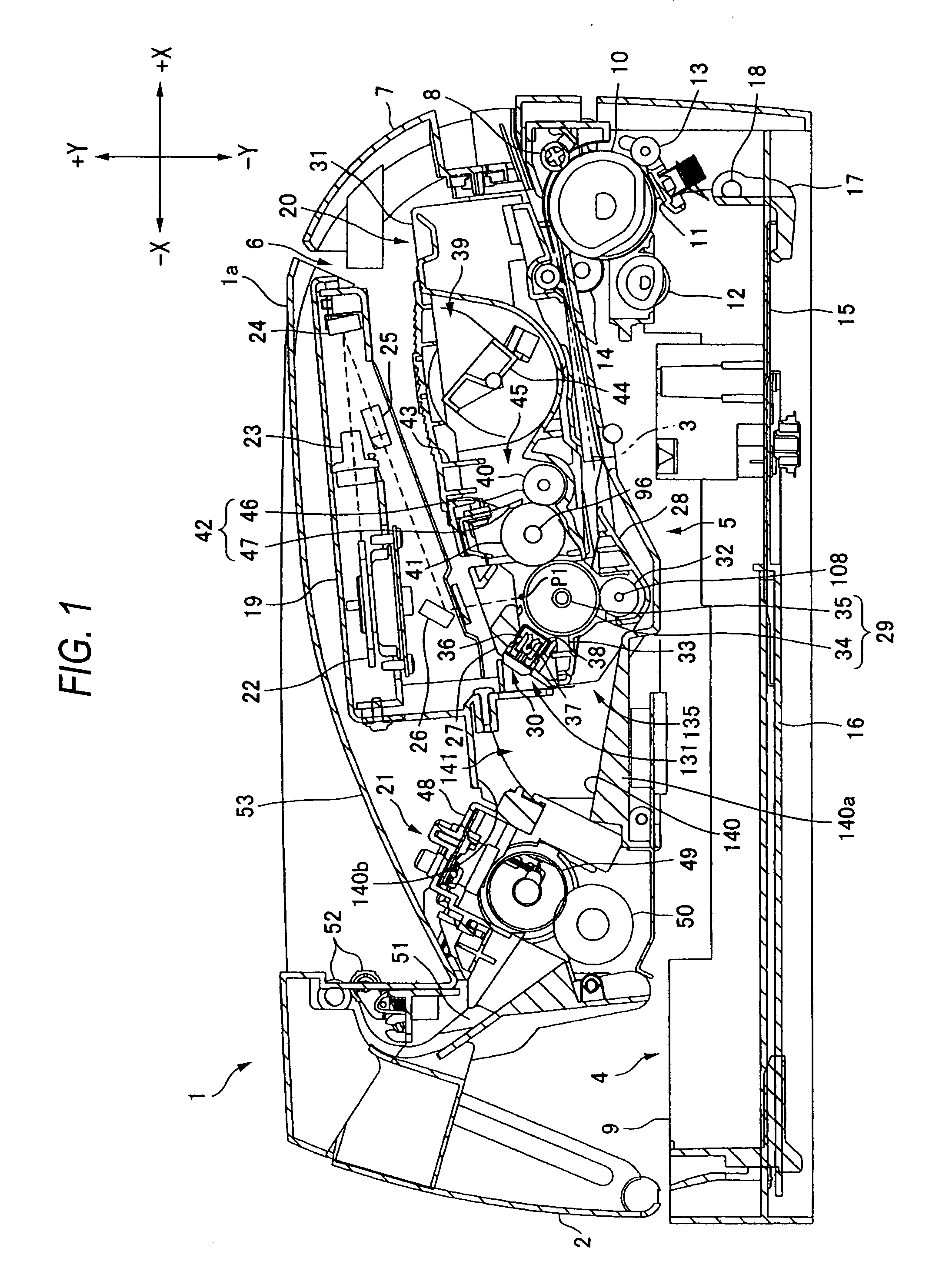
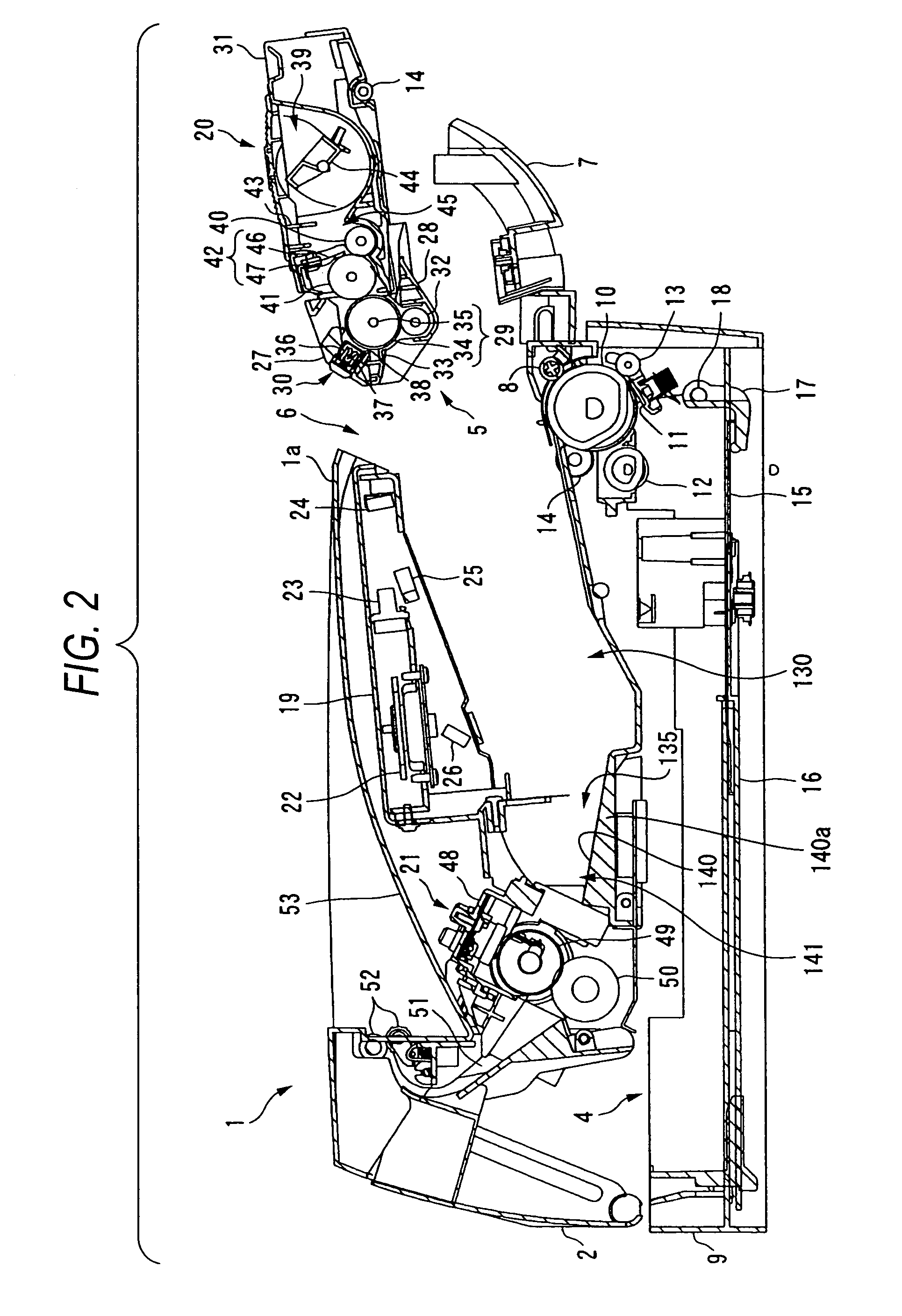
[0044]FIGS. 1 and 2 are side sectional views of a substantial part of a laser printer as an image forming apparatus according to the embodiment of the invention. The laser printer 1 is equipped with a main body casing 2, a feeder unit 4 for supplying a sheet 3 as a recording subject medium, an image forming unit 5 for forming an image on the sheet 3 supplied, and other units and components. The feeder unit 4 and the image forming unit 5 are housed in the main body casing 2.

[0045]A front wall of the main body casing 2 is formed with an attachment / detachment opening 6 for attachment and detachment of a process cartridge 20 (described later) as well as a front cover 7 for opening and closing the attachment / detachment opening 6. The front cover 7 is rotatably supported by a cover shaft (not shown) that is inserted in a bottom end portion of the front cover 7. With this structure, if the front cover 7 is closed by rotating it about the cover shaft, the attachment / de...

second embodiment

1. Total Configuration

[0146]FIGS. 13 and 14 are side sectional views of a substantial part of a laser printer as an image forming apparatus according to a second embodiment of the invention. FIG. 15 is a plan view of a process cartridge. FIG. 16 is a side view of the process cartridge. FIG. 17 is a perspective view showing the internal structure of a top frame and illustrating a discharge wire stretching structure.

[0147]The laser printer 201 is equipped with a main body casing 202, a feeder unit 204 for supplying a sheet 203 as a recording subject medium, an image forming unit 205 for forming an image on the sheet 203 supplied, and other units and components. The feeder unit 204 and the image forming unit 205 are housed in the main body casing 202.

[0148]A front wall of the main body casing 202 is formed with an attachment / detachment opening 206 for attachment and detachment of a process cartridge 220 (described later) as well as a front cover 207 for opening and closing the attachme...


PUM


Abstract

A charger is opposed to a charging subject member and charges the charging subject member by generating corona discharge. The charger includes: a discharge electrode; and a pair of facing electrodes that are disposed to face with each other being the discharge electrode interposed therebetween and arranged to be distant from the discharge electrode, wherein the facing electrodes are arranged that an interval between the facing electrodes gradually decreases towards the charging subject member.

Description

BACKGROUND OF THE INVENTION[0001]1. Field of the Invention[0002]The present invention relates to a charger, an image forming apparatus, and a process cartridge.[0003]2. Description of the Related Art[0004]Conventional image forming apparatus such as laser printers employ a technique of charging a photoreceptor by causing corona discharge using a charger. For example, JP-A-2003-287993 discloses a technique that a shutter, a duct, and an exhaust room surrounded by a partition member are formed above a scorotron charger and ozone is removed by sucking air so that an air flow occurs in a direction from a photoreceptor to the charger.[0005]Scorotron chargers having a discharge wire and a grind are known as chargers used for laser printers. For example, a scorotron charger disclosed in US2003 / 03485A1 (JP-A-2003-140438) is equipped with right and left side plates and a grid portion that is opposed to a discharge electrode. The grid portion is provided with grid wires and a surface plate th...

Claims


Application Information

Patent Timeline
Patent Type & Authority Patents(United States)
IPC IPC(8): G03G15/02
CPCG03G15/0291G03G2215/027
Inventor ITABASHI, NAONISHIMOTO, TAKAHIROKONDO, KUNIHIKOSATO, FUMIKAZUYOSHIYAMA, IKUNOBUSUZUKI, TSUTOMU
Owner BROTHER KOGYO KK
Why Eureka
Try Eureka