Work when ready load balancing using critical dates

a critical date and work load technology, applied in the field of scheduling work loads, can solve the problems of invariably inefficient scheduling, increased costs, and unused work force and material assets

Inactive Publication Date: 2008-04-08
AMERICAN TELEPHONE & TELEGRAPH CO
View PDF16 Cites 16 Cited by
  • Summary
  • Abstract
  • Description
  • Claims
  • Application Information

AI Technical Summary

Benefits of technology

[0005]In accordance with the present invention, a method of balancing workload using critical dates is provided. The method includes the following steps: (a) assigning a promised delivery date to orders received from customers; (b) identifying one or more tasks associated with each of the orders; (c) assigning an expedited date or a customer requested date to each of the tasks of some of the orders; (d) determining a work start date for each of the one or more tasks in each of the orders; (e) assigning a first priority to tasks having a work start date D; (f) assigning a second priority to tasks scheduled to begin on day D+n and having the expedited date; (g) assigning a third priority to tasks scheduled to begin on day D+n and having the customer requested date; (h) setting n equal to a value of 1; (i) working on tasks during a work shift based on order of priority, wherein work on a lower priority task is not commenced until work on all tasks with higher priorities has been completed; (j) increasing n by an increment of 1; and (k) repeating steps (g), (h), (i), (j) and (k) until the work shift for day D has ended.

Problems solved by technology

Without proper scheduling coordination, workforce and material assets go unused, waiting for a preceding task to be completed.
This type of inefficient scheduling invariably leads to delays and increased costs.
However, the existing methods of allocating resources do not recognize higher priority tasks and do not take into consideration client mandated completion dates.

Method used


Image

  • Work when ready load balancing using critical dates
  • Work when ready load balancing using critical dates

Examples


Embodiment Construction

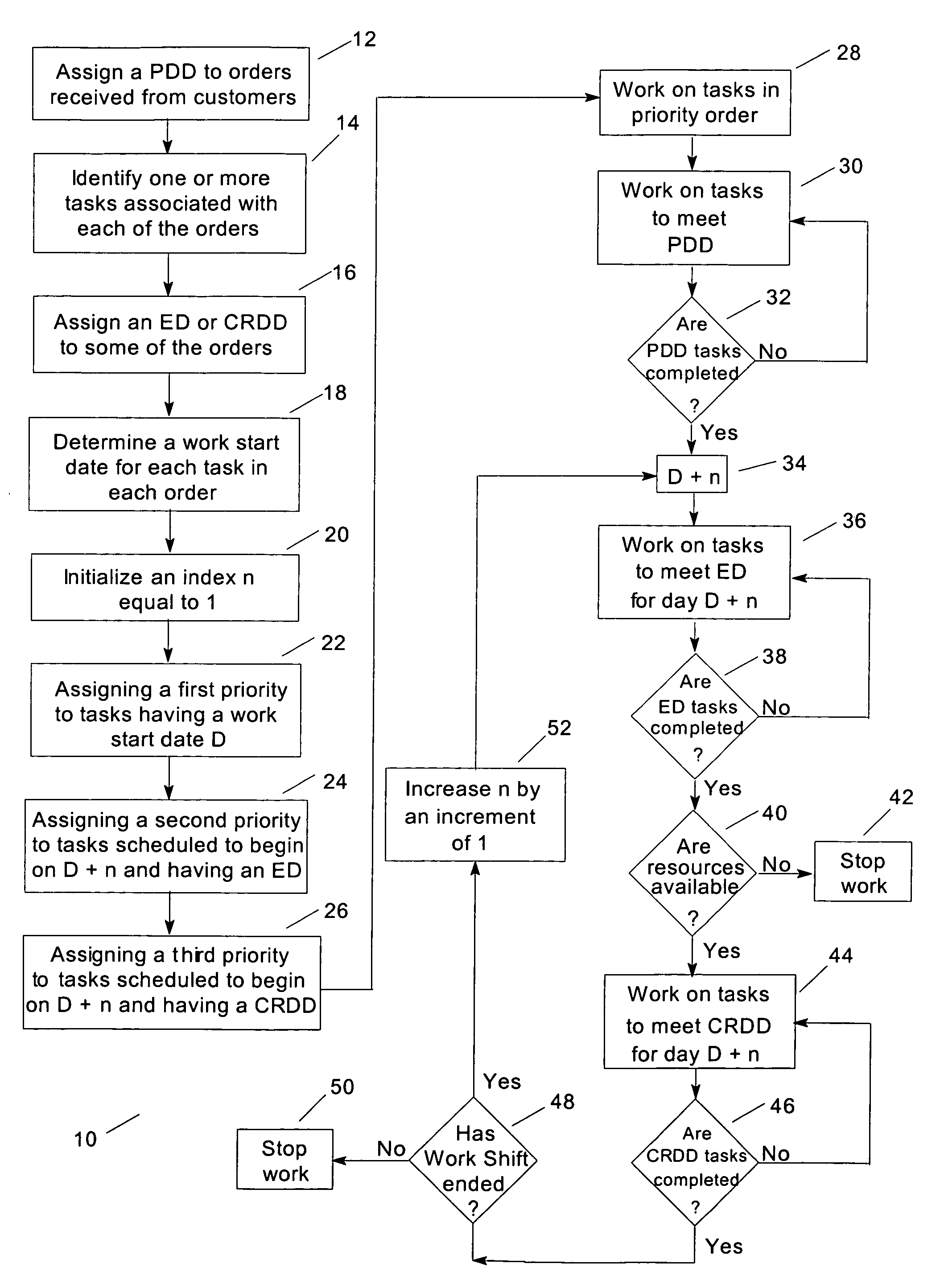
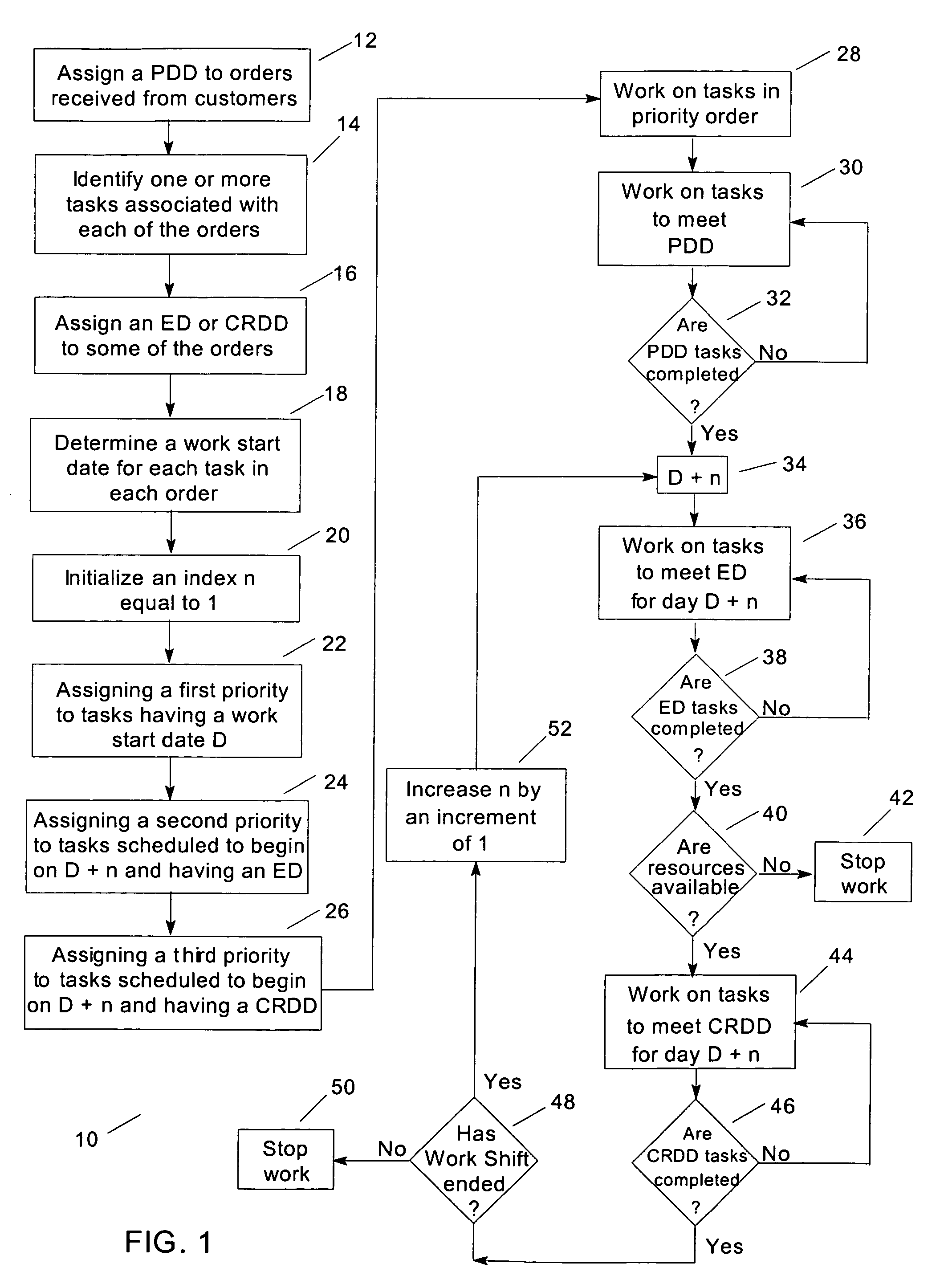
[0012]The present invention provides work load distribution for performing a complex sequence of tasks to complete an order for providing to a customer either a service or a product. In a preferred embodiment, the method is used in service assembly factories, for example provisioning a circuit in a telecommunications network. The resources needed can include work force and material assets and can vary for each order.

[0013]A service assembly factory is a sequence of many functions required to deliver a service to a customer. The final product can be access to a service such as frame relay or internet protocol (IP) and not physical goods. Assembling such a service requires connectivity of circuits and ports through a telecom company and its partner networks like the local exchange carriers (LECs). The telecom company as well as its partners have to coordinate and perform numerous tasks to deliver such a service on time. Because of the complexity of the service being assembled, the ass...


PUM


Abstract

A method of balancing workload using critical dates and including the following steps: (a) assigning a promised delivery date to orders received from customers; (b) identifying one or more tasks associated with each of the orders; (c) assigning an expedited date or a customer requested date to each of the tasks of some of the orders; (d) determining a work start date for each of the one or more tasks in each of the orders; (e) assigning a first priority to tasks having a work start date D; (f) assigning a second priority to tasks scheduled to begin on day D+n and having the expedited date; (g) assigning a third priority to tasks scheduled to begin on day D+n and having the customer requested date; (h) setting n equal to a value of 1; (i) working on tasks during a work shift based on order of priority, wherein work on a lower priority task is not commenced until work on all tasks with higher priorities has been completed; (j) increasing n by an increment of 1; and (k) repeating steps (g), (h), (i), (j) and (k) until the work shift for day D has ended.

Description

BACKGROUND OF INVENTION[0001]This invention relates to scheduling work loads in order to evenly distribute the work and the available staff based on critical dates for completion.[0002]In order to maintain a competitive position in industry, it is imperative for a company to efficiently and economically utilize its assets. This is especially important when the manufacturing and / or production process includes a series of interdependent sequential tasks, wherein the completion of one task is required before the next task can be started. Without proper scheduling coordination, workforce and material assets go unused, waiting for a preceding task to be completed. This type of inefficient scheduling invariably leads to delays and increased costs.[0003]Many different schemes have been proposed for addressing the issues of efficient scheduling and maximization of workforce assets. Workcenters today often use one of two load distribution models: (1) “work when ready” or (2) “work when criti...

Claims


Application Information

Patent Timeline
Patent Type & Authority Patents(United States)
IPC IPC(8): G06F19/00
CPCG06Q10/06
Inventor ABOUJAOUDE, ROGERESLAMBOLCHI, HOSSEINMCCANUEL, JOHNSHARIATI, SAEID
Owner AMERICAN TELEPHONE & TELEGRAPH CO
Why Eureka
Try Eureka