Initiator

a technology of initiator and tube, which is applied in the direction of electric fuze, pedestrian/occupant safety arrangement, vehicular safety arrangement, etc., can solve the problems of poor workability, low propagation efficiency of flame energy, and poor diversity in use manner, so as to reduce the thickness of the wall, enhance the trigger action, and strengthen the tubular portion of the capsul

Inactive Publication Date: 2008-04-15
TOYOTA JIDOSHA KK
View PDF33 Cites 39 Cited by
  • Summary
  • Abstract
  • Description
  • Claims
  • Application Information

AI Technical Summary

Benefits of technology

[0005]With this configuration, the plurality of rupture-accelerating means accelerates rupture of the tubular portion of the capsule upon ignition of the initiating explosive contained in the capsule. Therefore, in the case where the gas generator (gas-generating material) of the inflator is disposed outside the tubular portion of the capsule, flame energy can be efficiently propagated from the initiating explosive to the gas generator (gas-generating material) of the inflator, thereby enhancing a trigger action (ignitability) of the gas generator (gas-generating material) in the inflator.
[0014]In this case, the detonation-force-enhancing means may be implemented such that the amount of an initiating explosive for rupturing the tubular portion of the capsule is greater than that of an initiating explosive for rupturing the bottom portion of the capsule or such that an initiating explosive for rupturing the tubular portion of the capsule is greater in detonation force than an initiating explosive for rupturing the bottom portion of the capsule. In these cases, the detonation force imposed on the tubular portion of the capsule can be made greater than that imposed on the bottom portion of the capsule in a simple manner.

Problems solved by technology

As a result, the initiator provides poor diversity in its manner of use and may, in some cases, involve low propagation efficiency of flame energy to a gas-generating material contained in an inflator or poor workability in terms of connection of a connector to the electrode pins.

Method used


Image

  • Initiator
  • Initiator
  • Initiator

Examples


Embodiment Construction

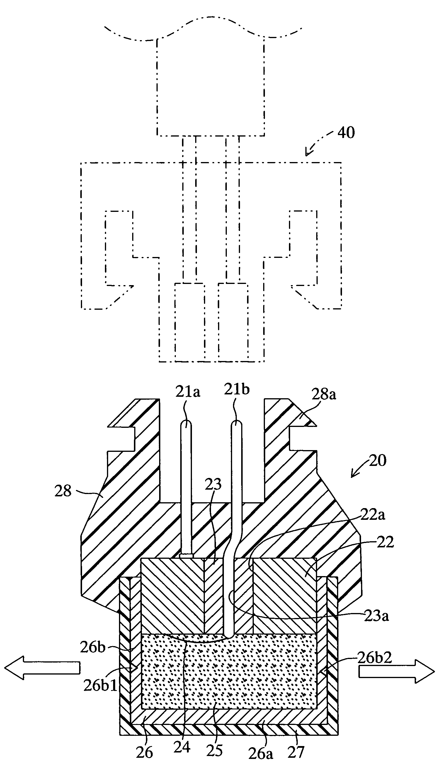
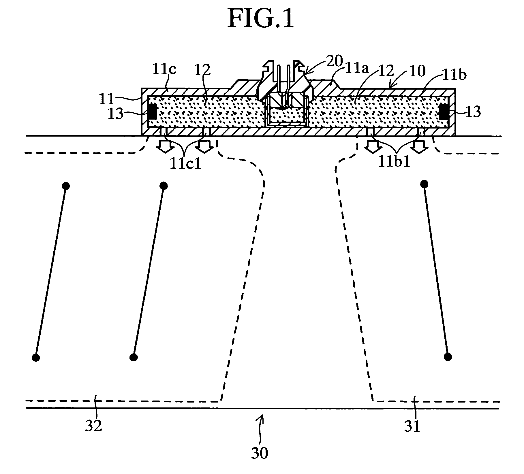
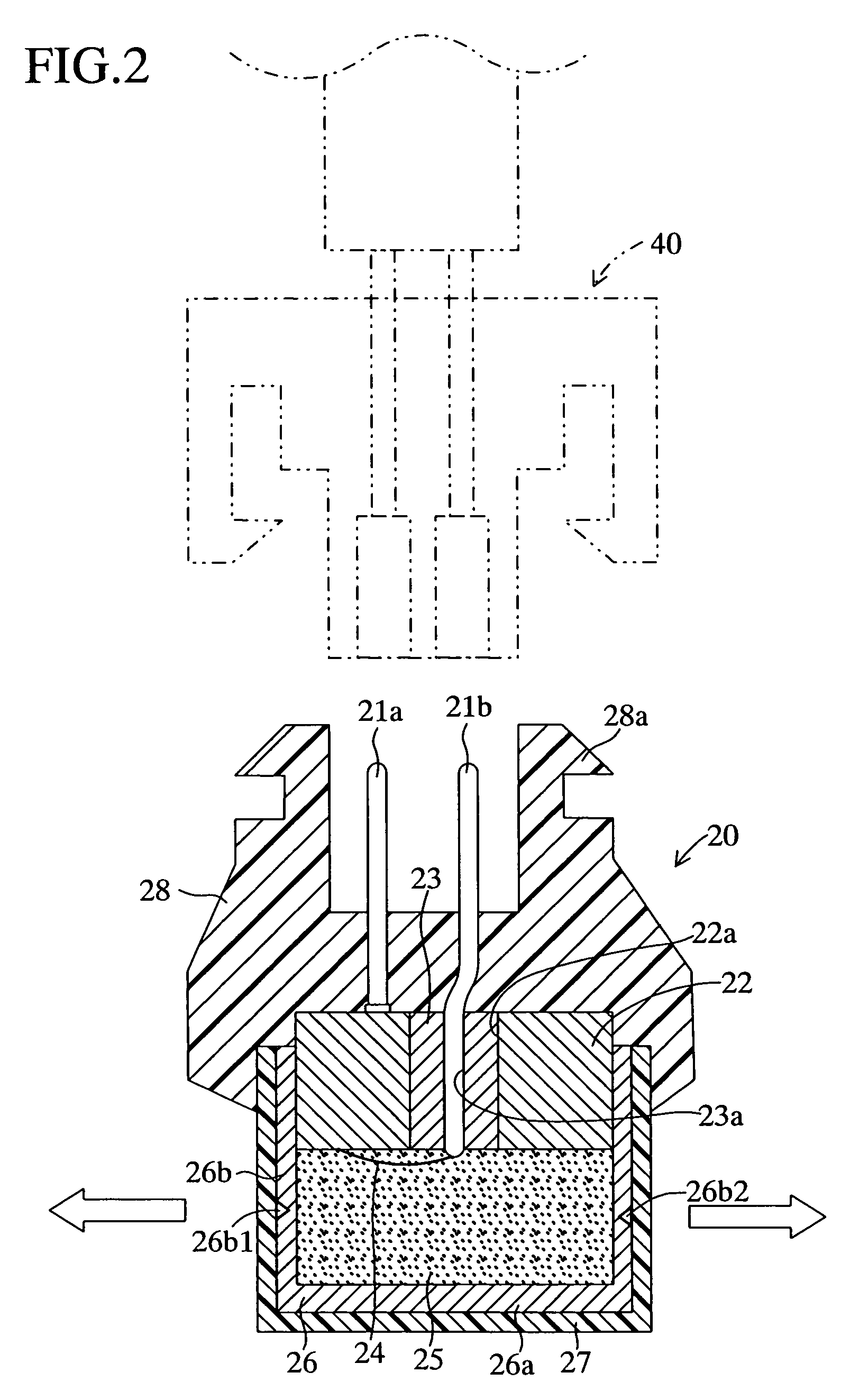
[0023]An embodiment of the present invention will now be described with the drawings. FIG. 1 shows an embodiment in which an initiator 20 according to an embodiment of the present invention is incorporated in an inflator for use in an air bag apparatus for protecting heads of persons sitting in front and rear seats of a vehicle. The inflator 10 includes a mounting portion 11a for mounting the initiator 20 and a casing 11. The mounting portion 11a is located at a longitudinally central portion of the inflator 10. The casing 11 includes a large chamber 11b and a small chamber 11c, which are located on the front and rear sides, respectively, of the mounting portion 11a and each contain a gas-generating material 12 and a combustion accelerator 13.

[0024]The casing 11 is disposed along the front-rear direction of a vehicle. The large-volume chamber 11b has gas outlet holes 11b1 through which gas is discharged into a front-seat-side inflation portion 31 of an air bag 30. The small-volume c...


PUM


Abstract

An initiator is incorporated in an inflator in order to trigger the inflator through propagation of flame from an initiating explosive to a gas generator of the inflator. The initiator includes a closed-bottomed tubular capsule for accommodating the initiating explosive. A tubular portion of the capsule includes a plurality of rupture-accelerating means (grooves each having a V-shaped cross section) for accelerating rupture upon ignition of the initiating explosive, whereby flame propagates from the initiating explosive to the gas generator of the inflator along a plurality of directions.

Description

TECHNICAL FIELD[0001]The present invention relates to an initiator to be incorporated in, for example, an inflator of an airbag apparatus to be mounted in a vehicle.BACKGROUND ART[0002]A conventional initiator of this kind includes a pair of electrode pins held together via an insulating member; a bridge wire connected to the electrode pins and generating heat upon energization; an ignitable material (an initiating explosive) which is ignited through exposure to heat generated by the bridge wire; and a casing (capsule) for accommodating the bridge wire and the ignitable material in a sealed condition, as disclosed in, for example, Japanese Patent Application Laid-Open (kokai) No. 11-301402.[0003]In the above-mentioned conventional initiator, the direction in which the electrode pins extend (hereinafter called the “extending direction”) and the flame propagation direction of the ignitable material (initiating explosive) are substantially the same (substantially aligned with each othe...

Claims


Application Information

Patent Timeline
Patent Type & Authority Patents(United States)
IPC IPC(8): B60R21/26F42B3/10B60R21/272B60R21/16B60R21/233B60R21/263B60R21/264F42B3/12
CPCF42B3/127B60R21/2644B60R2021/23316B60R2021/26029B60R21/26B60R21/263B60R21/272
Inventor TAKAHARA, ISAMUNOSE, KAZUOYOSHIGAI, AKITOSHI
Owner TOYOTA JIDOSHA KK
Why Eureka
Try Eureka