Cap assembly and container used therewith

a technology of cap assembly and container, which is applied in the field of cap assembly, can solve the problems of inability to substantially resist the sanitizing environment of the opening extending therethrough for dispensing purposes, the inability to seal over the dispensing opening often fails, and the difficulty of low acid applications

Active Publication Date: 2008-04-15
SCHOLLE IPN CORP
View PDF7 Cites 44 Cited by
  • Summary
  • Abstract
  • Description
  • Claims
  • Application Information

AI Technical Summary

Problems solved by technology

While the sterilization of containers for high acid products has been readily achieved, there have been problems associated with low acid applications.
Providing covers for fitments which are both suitable for use in low acid conditions, and which include openings extending therethrough for dispensing purposes cannot substantially withstand the sanitizing environment has proven difficult.
First, the seal over the dispensing opening often fails during the sanitizing procedure.
In either case, the end result is that the material within the container is destroyed and must be discarded.
Inasmuch as such sanitizing is highly destructive to fitments and covers, containers used for low acid applications generally include two separate fitments.
Problematically, the use of two separate fitments increases the cost of the containers, the assembly of the containers and the ease of manipulation of the containers.
Furthermore, the greater use of components leads to increased container failure rates.

Method used


Image

  • Cap assembly and container used therewith
  • Cap assembly and container used therewith
  • Cap assembly and container used therewith

Examples


Embodiment Construction

[0042]While this invention is susceptible of embodiment in many different forms, there is shown, in the drawings, several specific embodiments with the understanding that the present disclosure is to be considered as an exemplification of the principles of the invention and is not intended to limit the invention to the embodiments illustrated.

[0043]It will be understood that like or analogous elements and / or components, referred to herein, are identified throughout the drawings by like reference characters. In addition, it will be understood that the drawings are merely representations of the present invention, and some of the components may have been distorted from actual scale for purposes of pictorial clarity.

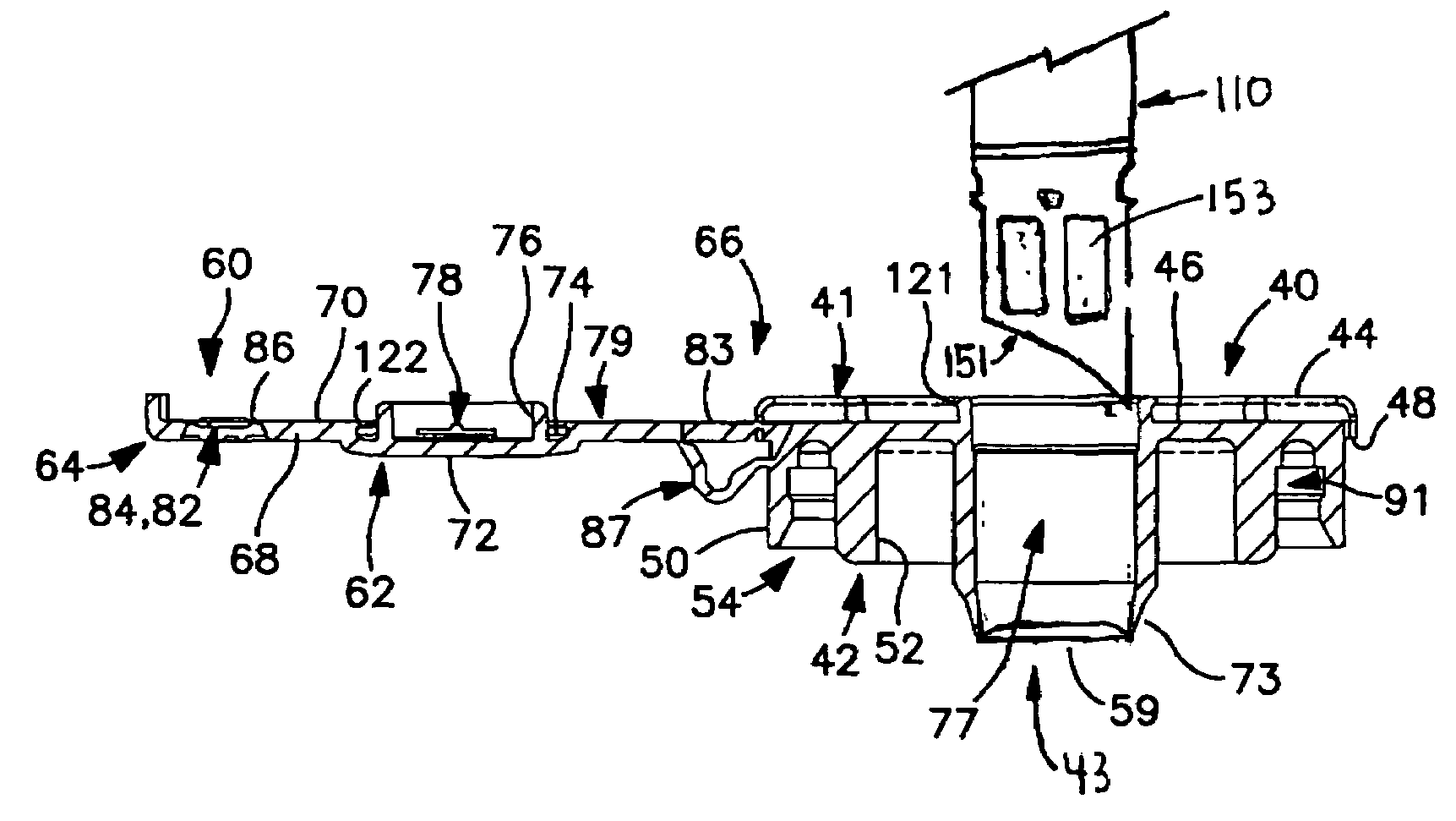
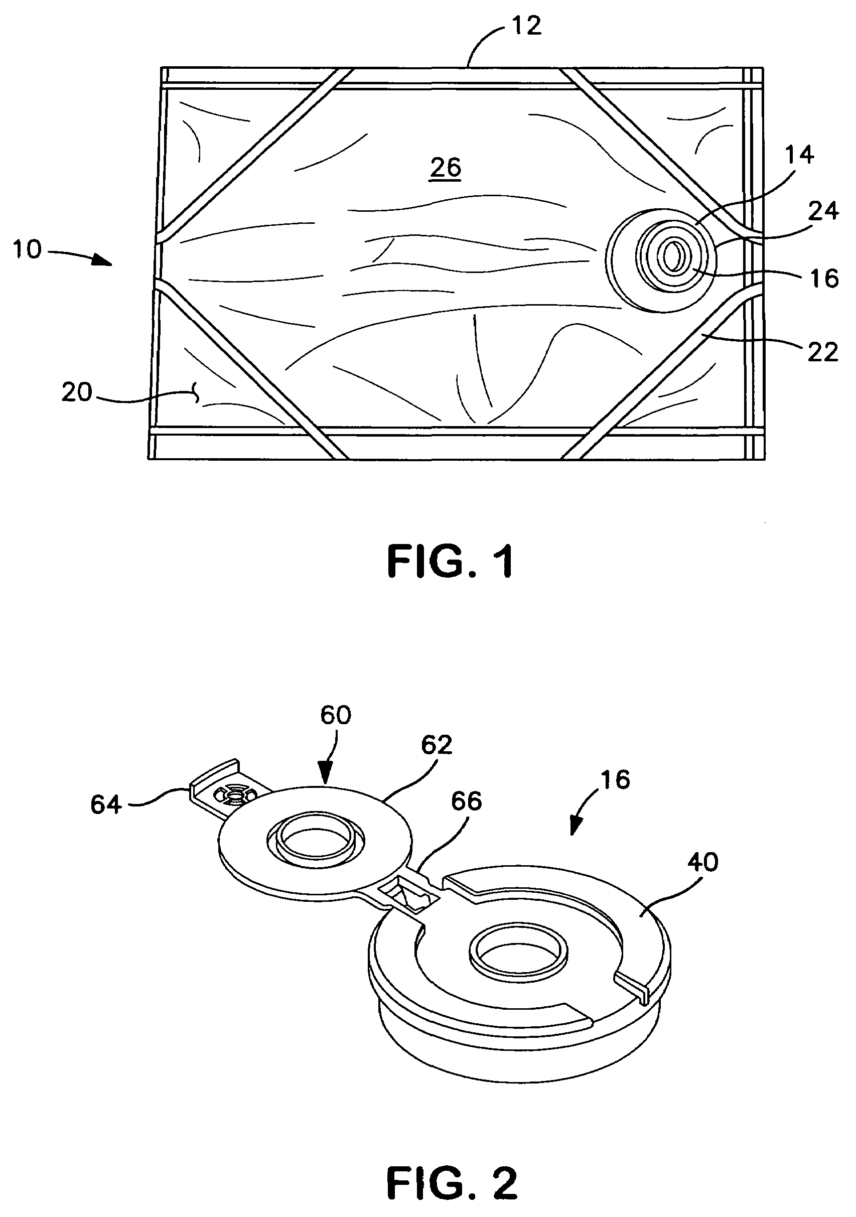
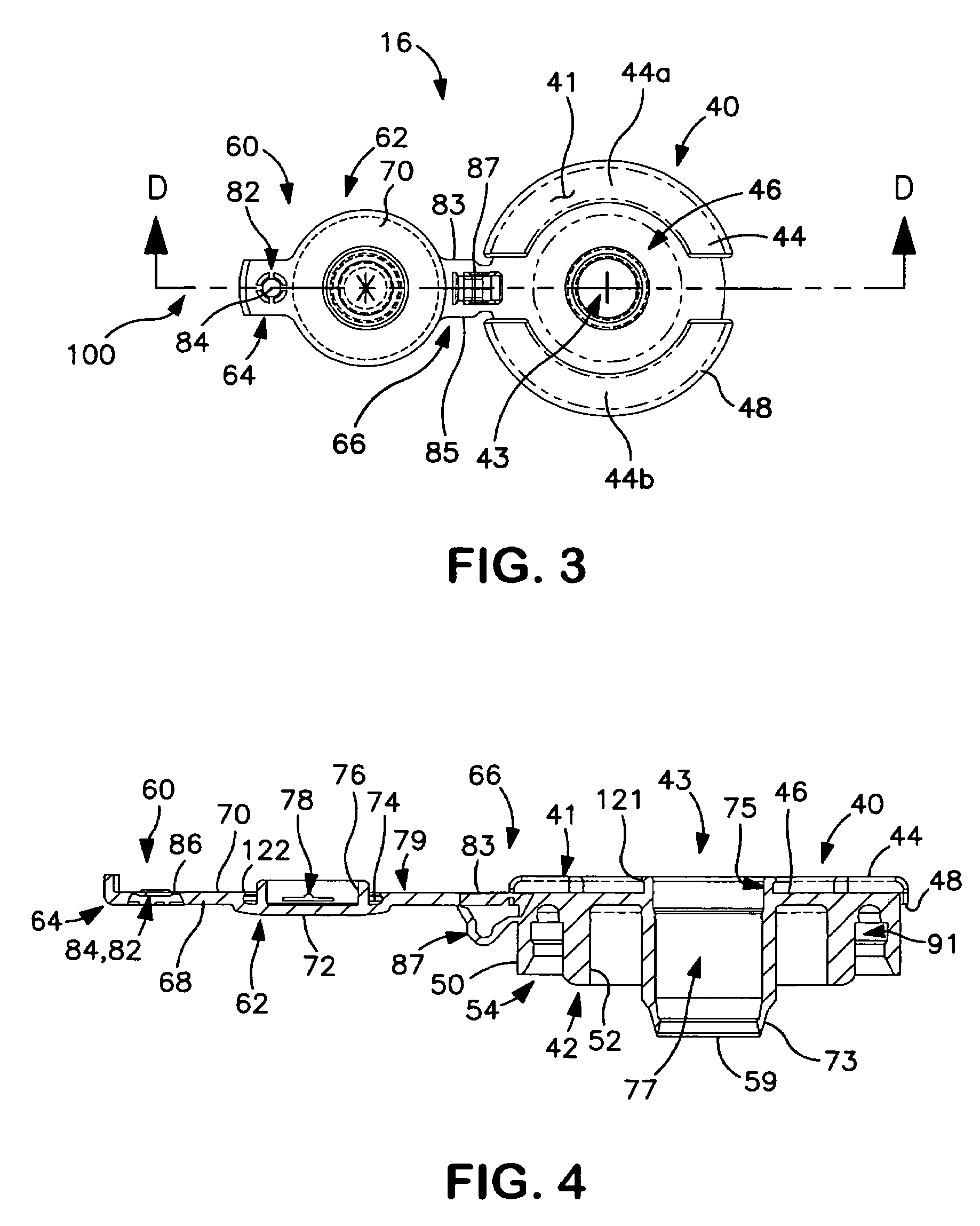
[0044]Referring now to the Figures, and in particular to FIG. 1, container assembly 10 includes container body 12, fitment 14 and cap assembly 16. Container body 12 comprises a plurality of panels 20 and a plurality of seals 22. The panels and seals cooperate to define cavit...


PUM

PropertyMeasurementUnit
temperatureaaaaaaaaaa
temperaturesaaaaaaaaaa
pressureaaaaaaaaaa

Abstract

A container assembly having a container, a fitment and a cap assembly. The container has at least one panel and at least one seal sealing the at least one panel to define a cavity. The fitment is coupled with the container, comprising a body having a first end and a second end. The second end extends away from the container, wherein the fitment provides fluid communication with the cavity. The cap assembly is releasably attachable to the second end of the fitment. The cap assembly comprises a base and a cover. The base includes an upper surface, a lower surface and an opening extending therethrough. The opening including an upper annular rim extending from the upper surface of the base and a lower annular rim extending from the lower surface of the base. The cover is attachable to the base to cover the opening. The cover includes an annular ring that extends along at least a portion of the upper annular rim of the opening. The annular ring forms a hermetic seal with the upper annular rim of the opening. A frangible cover is integrally molded with the cap extending across the lower annular rim.

Description

[0001]This application is a continuation in part of U.S. patent application Ser. No. 10 / 929,663 filed Aug. 30, 2004 entitled “Cap Assembly and Container Used Therewith”, the entire specification of which is incorporated by reference.BACKGROUND OF THE INVENTION[0002]1. Field of the Invention[0003]The present invention relates in general to a cap assembly, and more particularly, to a cap assembly capable of hermetically sealing a container assembly, the cap assembly undergoing sterilization processes with superheated steam at temperatures in excess of 280° F. Such sterilization processes are generally suitable for filling of food grade flowable material including low acid flowable material. Of course, the invention is not limited to any particular flowable material.[0004]2. Background Art[0005]The use of flexible containers for the shipment and dispensing of flowable material has greatly increased in recent years. Increasingly, flexible containers are common for food grade products. A...

Claims


Application Information

Patent Timeline
Patent Type & Authority Patents(United States)
IPC IPC(8): B67B5/00B67D99/00
CPCB65D47/0814B65D47/121B65D51/20B65D75/5877B65D2251/0025B65D2251/0096
Inventor VERESPEJ, ROCKLINHARTMAN, LUKEKNAACK, CRAIG F.SLEVIN, DAVID
Owner SCHOLLE IPN CORP
Why Eureka
Try Eureka