Rotary recliner mechanism for use with a vehicle seat assembly

a technology of rotary recliner and vehicle seat, which is applied in the direction of vehicle seats, movable seats, vehicle arrangements, etc., can solve the problems of difficult mass production, troublesome recliner, and free play in the seat back

Active Publication Date: 2008-04-22
FAURECIA AUTOMOTIVE SEATING CANADA
View PDF42 Cites 43 Cited by
  • Summary
  • Abstract
  • Description
  • Claims
  • Application Information

AI Technical Summary

Benefits of technology

[0007]In accordance with the present invention there is disclosed a rotary recliner mechanism for pivotally interconnecting a seat back member and a seat cushion member of a vehicle seat assembly. The rotary recliner mechanism includes first and second plate members that are adapted to be securely mounted one each on the seat cushion member and the seat back member. The second plate member is rotatably supported by the first plate member so as to define a substantially horizontal seat pivot axis. A ring gear is formed on the second plate member, and a first pair of elongate guide members is formed on the first plate member. The pair of guide members defines a guide channel therebetween that is oriented along a substantially radial axis. The rotary recliner mechanism also includes an elongate first locking pawl that has a longitudinal pawl axis and is disposed within the guide channel for sliding movement therealong. The pawl has inner and outer end portions, with the outer end portion located radially outward of the inner end portion. The outer end portion has a gear segment formed thereon that is engagable with the ring gear in locked relation. The pawl also has a pair of opposite side edges slidably engagable with the pair of elongate guide members. Each of the opposite side edges extends between the inner and outer end portions. The pawl additionally has a driven lobe arranged on the inner end portion in substantially off-set relation from the longitudinal pawl axis. The driven lobe includes a cam-follower surface. The rotary recliner mechanism additionally includes a cam member that is mounted for rotation about the pivot axis between a locked position and an unlocked position relative to the first and second plate members. The cam member has a first foot portion that is provided with an active lobe arranged thereon. The active lobe includes a camming surface that is arranged eccentrically of the pivot axis and is engagable with the cam-follower surface. According to the invention, in the locked position, the camming surface engages the cam-follower surface, with the pawl being engaged by the cam member solely at the cam-follower surface, and with the longitudinal pawl axis being substantially askew (hereinafter, alternately referred to as “angularly offset”) relative to the radial axis, such that the gear segment securely engages the ring gear in the locked relation, and such that rotation of the second plate member about the pivot axis is substantially restrained relative to the first plate member. In the unlocked position, the gear segment is removed from the ring gear, so as to enable rotation of the second plate member about the pivot axis relative to the first plate member. In this manner, rotation of the cam member selectively controls pivotal movement of the seat back member about the pivot axis relative to the seat cushion member.

Problems solved by technology

While such rearward and forward forces are generally generated during normal vehicle movement, the free play in the seat back that is inherent during these non-locking conditions of the recliner may be troubling, inter alia, from a safety perspective.
Though not essential to an understanding of the present invention, the tolerancing that has heretofore been required between the cams and the cam shoulders of such prior art rotary recliners, in order to effect the purportedly required balanced distribution of forces, has generally been seen to be costly and difficult to achieve in mass-production, with a relatively high incidence of component rejection and / or failure.

Method used


Image

  • Rotary recliner mechanism for use with a vehicle seat assembly
  • Rotary recliner mechanism for use with a vehicle seat assembly
  • Rotary recliner mechanism for use with a vehicle seat assembly

Examples


Embodiment Construction

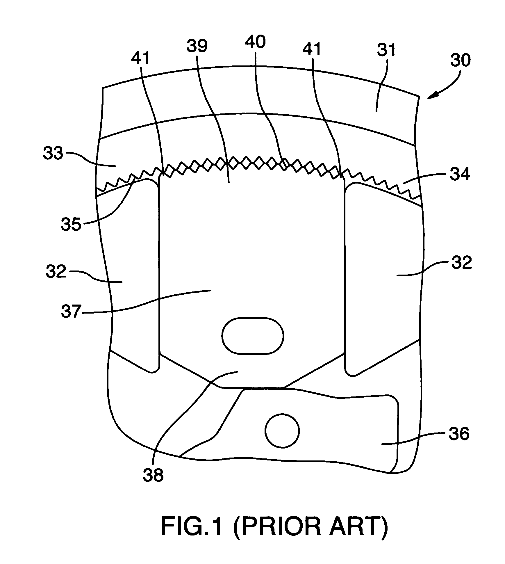
[0033]Generally, in the prior art, and with general reference to FIG. 1, rotary recliners 30 have heretofore included a fixed plate 31 rotatably supporting a mobile plate 33. Typically, the fixed and mobile plates 31, 33 have respectively been mounted on a vehicle seat cushion and a seat back (not shown). Relevant portions of one such prior art rotary recliner 30 are shown in FIG. 1. The rotary recliner 30 shown in FIG. 1 includes a rotatable cam 36 that is engagable with an inner end 38 of a pawl 37. As shown in FIG. 1, the pawl 37 is supported between guides 32 provided on the fixed plate 31, and each pawl 37 includes a toothed gear segment 39. In the prior art, the toothed gear segment 39 has been designed to be selectively and securely engagable with a corresponding toothed ring gear 34 provided on the mobile plate 33. As described in greater detail elsewhere herein, however, it has thus far been difficult to ensure the desired locking of the mobile plate 33 relative to the fixe...


PUM


Abstract

A rotary recliner includes rotatable plate members that pivotally interconnect a vehicle seat back and cushion. A pawl defines a pawl axis and slides between a guide pair on one plate member. An outer end of the pawl includes a gear segment that is lockable with a ring gear on the other plate member. A cam rotates between locked and unlocked positions, and has a camming surface eccentric of the pivot axis. When locked, the camming surface engages a cam-follower surface on the pawl, with the pawl being engaged by the cam solely at the cam-follower surface, and with the pawl axis being askew of a radial axis, such that the gear segment locks with the ring gear, and such that the plate members are restrained from rotating. When unlocked, the gear segment is removed from the ring gear, such that the plate members may be rotated.

Description

FIELD OF THE INVENTION[0001]The present invention relates to the field of vehicle seat assemblies, and more particularly, to a rotary recliner for pivotally interconnecting a seat back member and a seat cushion member of a vehicle seat assembly.BACKGROUND OF THE INVENTION[0002]Automotive vehicles commonly have seat assemblies that permit the seat back to be selectively reclined, about a horizontal pivot axis, through a range of substantially upright, occupiable positions for selection by the user of a preferred seating position. In the past, rotary recliner mechanisms have proven an effective way to provide such reclining functionality in vehicle seat assemblies. Advantages of known rotary recliner mechanisms include that they are relatively inexpensive to manufacture, that they have their working components substantially enclosed (which lends to their reliability and safety), and that they fit into a relatively small design envelope. One prior art rotary recliner mechanism is discl...

Claims


Application Information

Patent Timeline
Patent Type & Authority Patents(United States)
IPC IPC(8): B60N2/02
CPCB60N2/2356B60N2/236
Inventor SMUK, WOJCIECH
Owner FAURECIA AUTOMOTIVE SEATING CANADA
Why Eureka
Try Eureka