Electronic scale and method for weight measurement including correction means for correcting a weight dependent signal

a technology of electronic scales and weights, applied in drying machines, drying, light and heating equipment, etc., can solve the problem of weighing values that are outside of specifications, and achieve the effect of reducing tim

Active Publication Date: 2008-04-22
SARTORIUS LAB INSTR GMBH & CO KG
View PDF3 Cites 10 Cited by
  • Summary
  • Abstract
  • Description
  • Claims
  • Application Information

AI Technical Summary

Benefits of technology

[0007]An object of the invention is to substantially reduce the time required to reach the full accuracy of an electronic scale after connection of the voltage supply.SUMMARY OF THE INVENTION
[0010]The magnitude of the initial correction value depends on how long the scale had been disconnected before being reconnected. Hereinafter, the length of time the scale had been disconnected before being reconnected is referred to as the OFF time or duration. In a first exemplary embodiment, the OFF time is determined by a clock component, for example a commercially available electronic clock component. Because the accuracy requirements for determining this time period are not very high and it is primarily a matter of determining shorter OFF times, even a capacitor slowly discharging via a resistor is suitable as a clock component. For example, it makes little difference whether the scale was turned off for two hours or for a longer period of time, such as for four hours. The capacitor is always charged to a fixed voltage when the scale is connected and gradually discharges while it is disconnected. The residual voltage present when the voltage supply is reconnected is then used as a measure for the OFF time. Modern capacitors make it possible to achieve a time constant of twenty minutes, for example, so that the critical OFF times from one minute up to one hour can be measured with sufficient accuracy.

Problems solved by technology

As such, there is a risk, particularly in high-resolution scales, that the weighing values will lie outside of specifications.

Method used


Image

  • Electronic scale and method for weight measurement including correction means for correcting a weight dependent signal
  • Electronic scale and method for weight measurement including correction means for correcting a weight dependent signal
  • Electronic scale and method for weight measurement including correction means for correcting a weight dependent signal

Examples


first embodiment

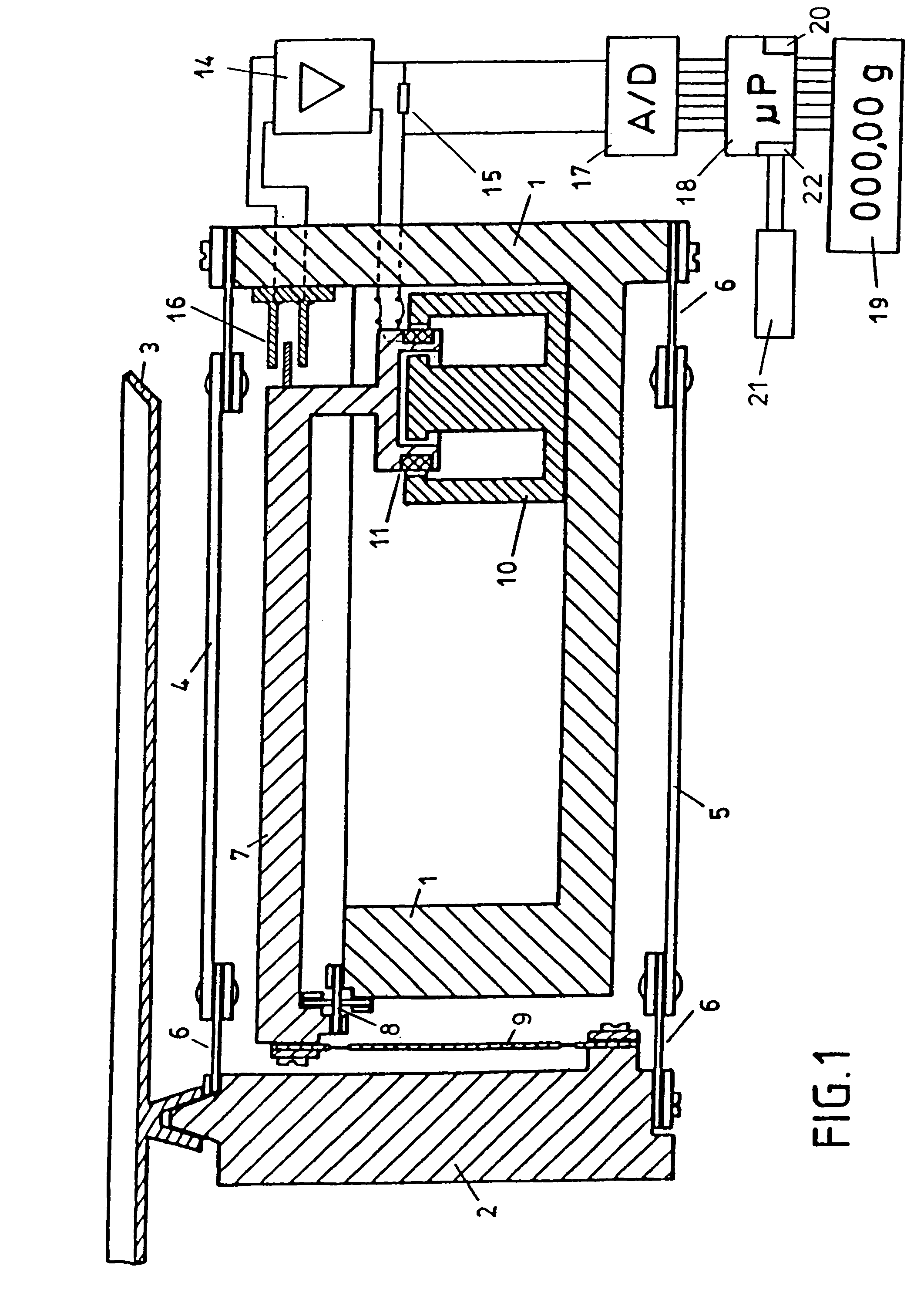
[0029]A second exemplary embodiment of the scale is depicted in FIG. 4. Components 1 through 20 correspond to the first embodiment shown in FIG. 1 and are therefore not described again here. The exemplary embodiment of the scale according to FIG. 4 includes a temperature sensor 41 in proximity of the electronics (A / D converter 17 and digital signal processing unit 18). This temperature sensor is used to indirectly determine the OFF duration. Its function will now be described with reference to FIG. 5. If the scale was turned off for a long time, the temperature measured by the temperature sensor 41 is the same as the ambient temperature (point 42). If the scale is connected at time t=0, the temperature measured by the temperature sensor 41 rises in accordance with the depicted curve 44 and finally reaches the steady end value 43. On the other hand, if the scale, at the same ambient temperature, is disconnected only briefly before being reconnected, the temperature measured by the te...

second embodiment

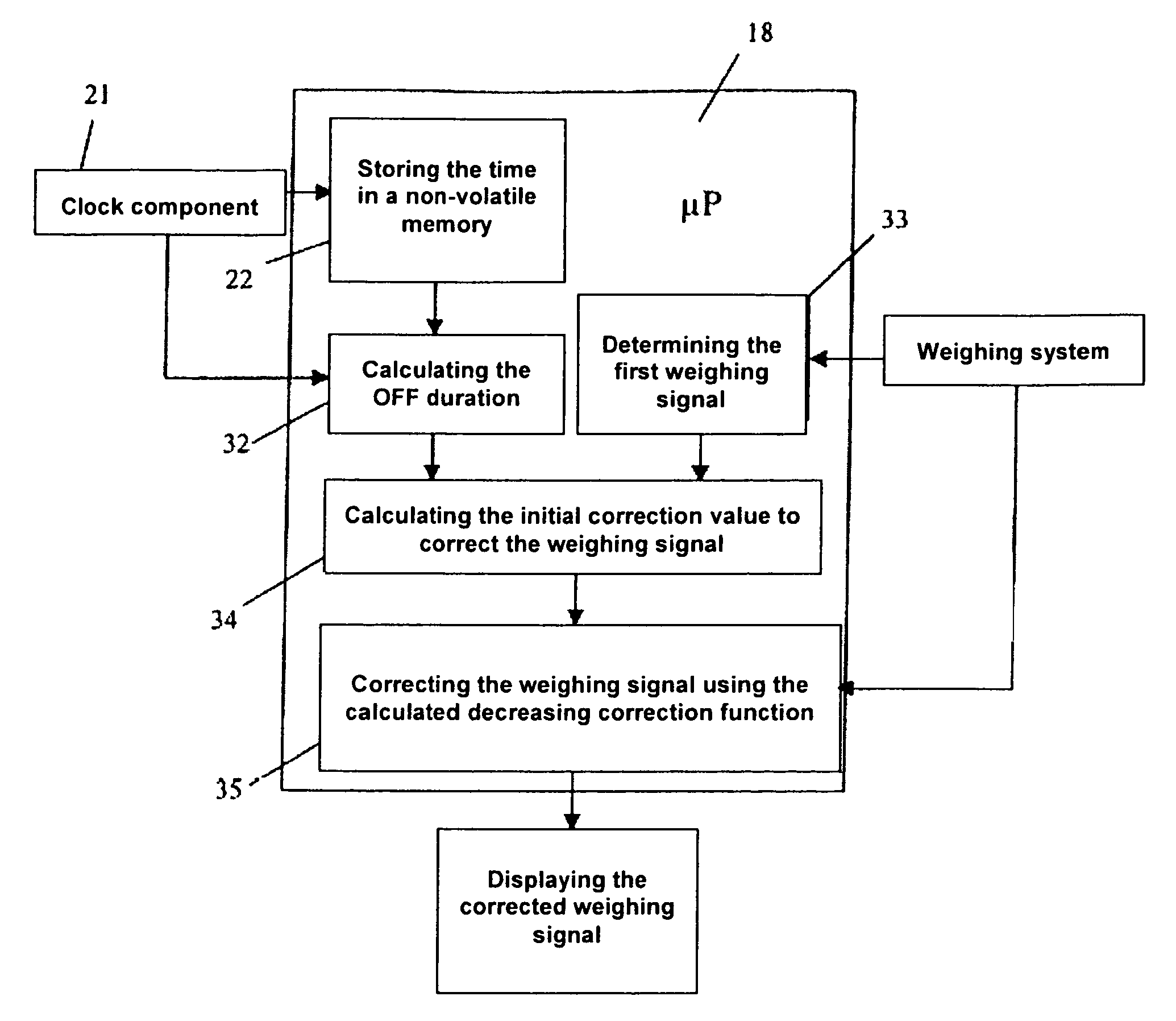
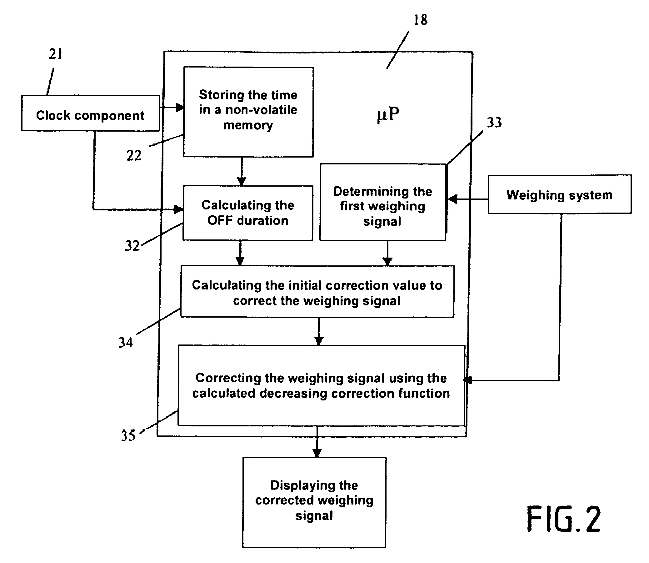
[0030]The block diagram pertaining to this second embodiment and illustrating this function is depicted in FIG. 6. FIG. 7 shows the associated flow diagram. The two representations correspond to FIGS. 2 and 3 and are self-explanatory to one of ordinary skill in the art based on the comments provided above.

[0031]FIG. 8 shows a third exemplary embodiment of a scale according to the present invention. Components 1 through 20 correspond to the first embodiment illustrated in FIG. 1 and are therefore not described again here. The embodiment of the scale according to FIG. 8 has both a temperature sensor 41 near the electronic components and a temperature sensor 51 remote from all heat-generating components. In FIG. 8, this temperature sensor 51 is shown on the support member 1, which is connected to the housing of the scale (not depicted) in a thermally highly conductive manner. If the scale is turned off for a prolonged period of time, both temperature sensors 41 and 51 are at ambient te...


PUM


Abstract

A scale having an electronic weighing system to generate a weight-dependent signal and a digital signal processing unit (18). The digital signal processing unit (18) has a circuit or program parts which measure the time elapsed since connection of the voltage to the scale. To dramatically reduce the time required for the scale to reach its full accuracy after connection of the voltage supply, the digital signal processing unit (18) has computation modules (34, 35) that correct the weight-dependent signal generated by the weighing system by a correction value that depends on the time elapsed. The magnitude of this correction value, starting from an initial correction value, converges with increasing time elapsed to a constant end value that differs from the initial correction value.

Description

[0001]This is a Continuation of International Application PCT / EP2004 / 011033, with an international filing date of Oct. 2, 2004, which was published under PCT Article 21(2) in German, and the disclosure of which is incorporated into this application by reference.BACKGROUND OF THE INVENTION[0002]1. Field of the Invention[0003]Apparatuses and methods consistent with the present invention relate to scale having an electronic weighing system and a digital signal processing unit. The electronic weighing system generates a weight-dependent signal, and the digital signal processing unit has circuit or program parts that detect the time elapsed since the connection of a voltage supply to the scale. The time elapsed is used to determine a correction value for correcting the weight-dependent signal.[0004]2. Description of the Related Art[0005]Scales of this type are known, for example, from U.S. Pat. No. 4,763,739. The circuit or program parts that detect the time elapsed since the connection ...

Claims


Application Information

Patent Timeline
Patent Type & Authority Patents(United States)
IPC IPC(8): H05B1/02G01G23/48
CPCG01G23/48
Inventor VON STEUBEN, JANMUELLER, MICHAELKLAUER, ALFRED
Owner SARTORIUS LAB INSTR GMBH & CO KG
Why Eureka
Try Eureka