Methods and apparatus for magnetic article detection

a detection method and detector technology, applied in the direction of linear/angular speed measurement, instruments, devices using electric/magnetic means, etc., can solve the problems of inaccurate output signals and the inability of the output of pdac and ndac to accurately indicate the positiv

Active Publication Date: 2008-04-22
ALLEGRO MICROSYSTEMS INC
View PDF9 Cites 168 Cited by
  • Summary
  • Abstract
  • Description
  • Claims
  • Application Information

AI Technical Summary

Benefits of technology

[0013]With this arrangement, once it is determined that the running mode detector output signal is accurate, the TPOS threshold signal is incrementally adjusted so as to advantageously reduce the phase error associated with consecutive detections by the TPOS detector and the running mode detector. By tailoring the step size of the TPOS threshold increments according to the AGC circuit, the TPOS threshold signal is adjusted in as short an amount of time as possible while still limiting phase error to below an acceptable limit.
[0017]With this arrangement, the PDAC and NDAC signals are updated to remain a desired percentage of the peak-to-peak magnetic field sensor signal, but without unnecessary signal updates.

Problems solved by technology

Some circuits for detecting moving or passing magnetic articles do not provide an accurate output signal immediately upon power up and / or down to zero speed of the magnetic article.
However, the outputs of the PDAC and the NDAC may not be accurate indications of the positive and negative peaks of the magnetic field signal until several cycles of the signal (i.e., signal peaks) occur.

Method used


Image

  • Methods and apparatus for magnetic article detection
  • Methods and apparatus for magnetic article detection
  • Methods and apparatus for magnetic article detection

Examples


Embodiment Construction

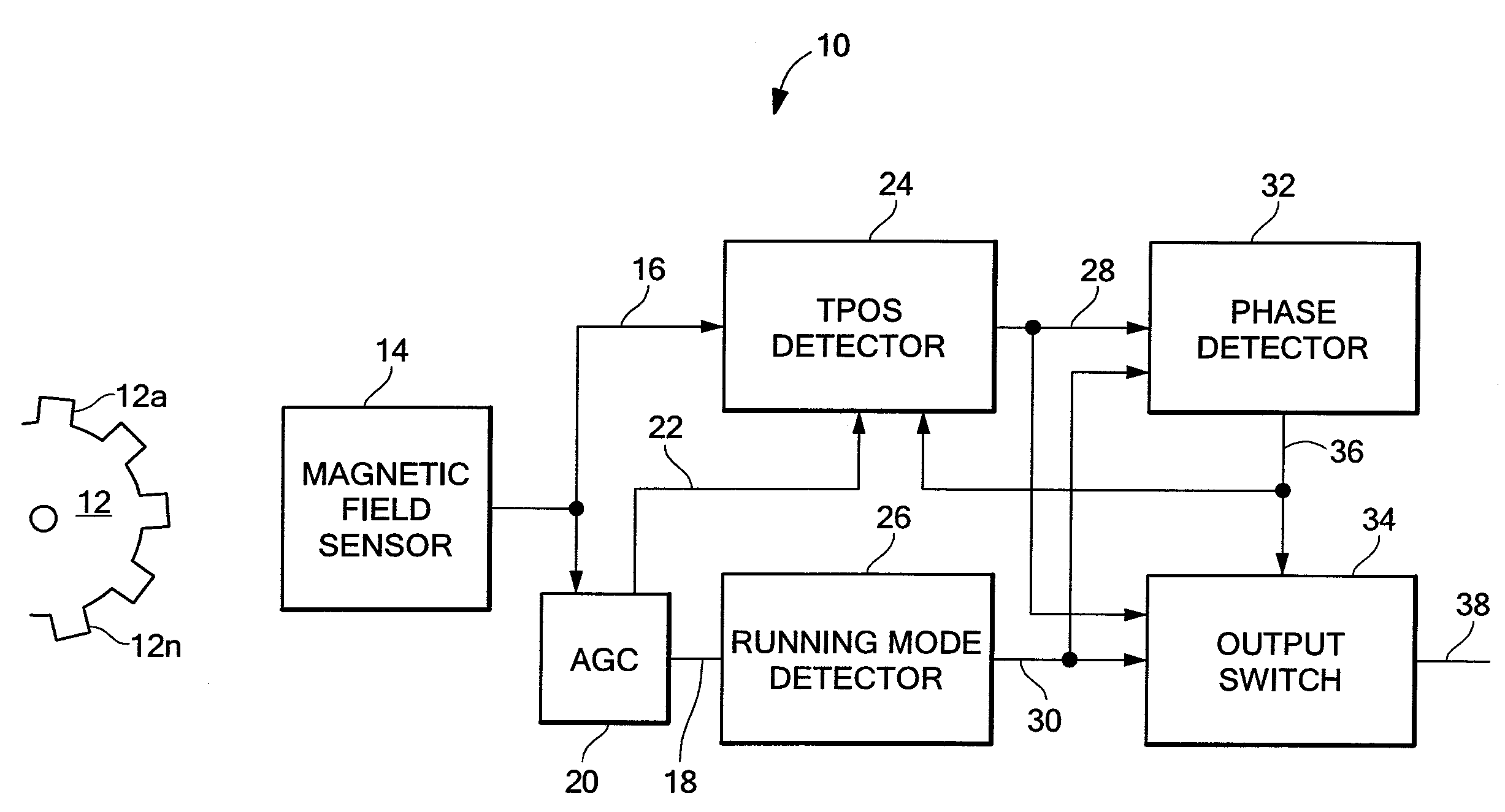
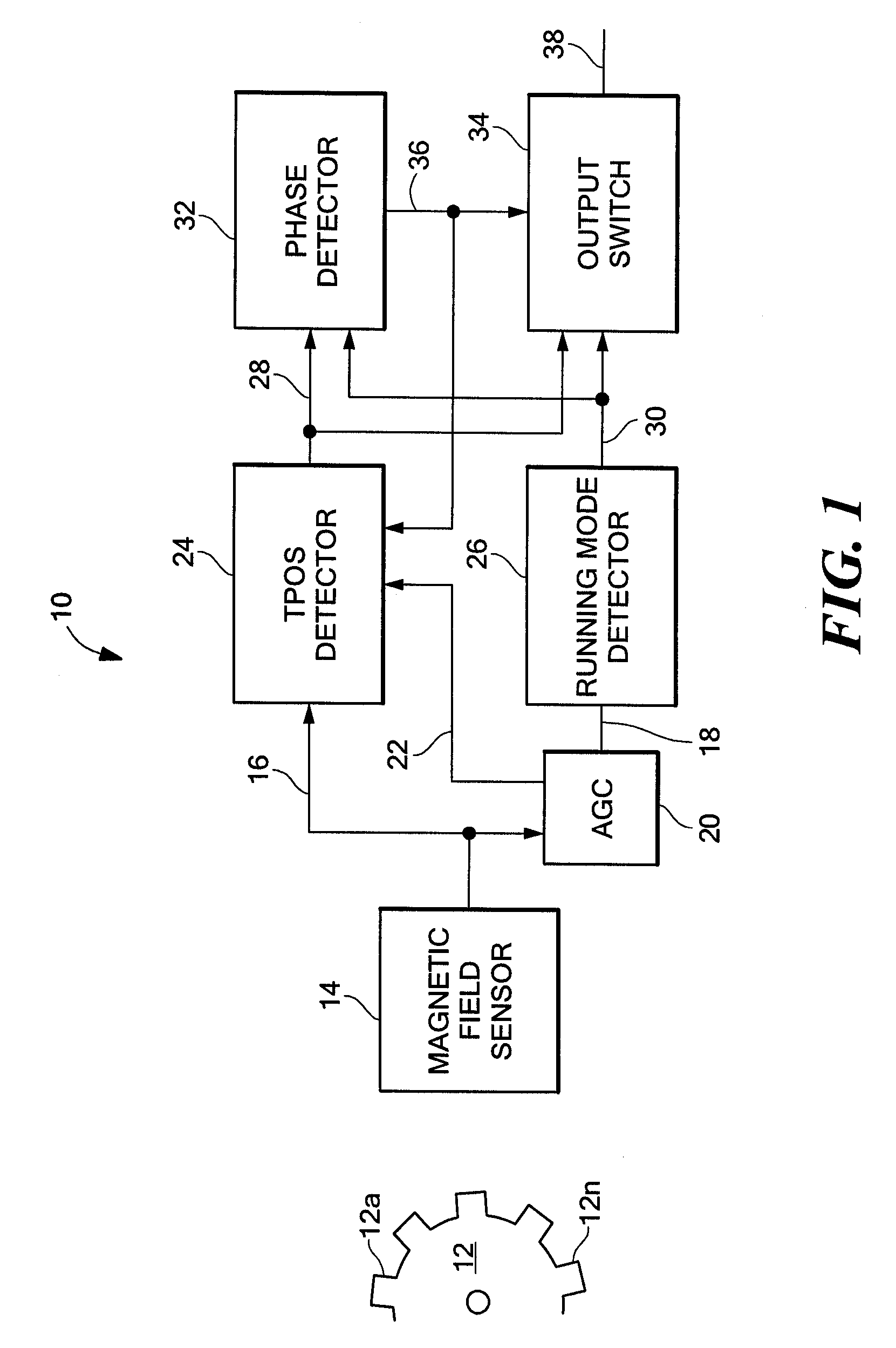
[0050]Referring to FIG. 1, a magnetic article detector 10 includes a magnetic field sensor 14 providing a magnetic field sensor signal 16 that is proportional to an ambient magnetic field. The detector 10 is positioned in proximity to a magnetic article, for example a gear 12, so that the magnetic field sensor signal 16 is indicative of the profile of the magnetic article 12. The detector 10 provides a detector output signal 38 indicative of the magnetic article 12 as it passes through the ambient magnetic field and here, a pulse train having transitions indicating edges of the gear teeth 12a-12n.

[0051]Preferably, each detection of a particular feature of the passing magnetic article 12 occurs at the same point on the magnetic field sensor signal 16. A variation in the phase of detections of the same feature on different revolutions of the magnetic article or of different features on the same revolution is referred to as an error or jump in the phase of the detector output signal 3...


PUM


Abstract

Apparatus and methods for detecting passing magnetic articles using a first, True Power On State (TPOS) detector during a first time interval and transitioning to a second, running mode detector after the first time interval, when the output of the second detector is accurate. A phase comparator is responsive to the output signal of the first and second detectors and provides a control signal indicative of a change in the phase relationship between the two output signals. An output switch controlled by the phase comparator provides, as the detector output signal, the first detector output signal during the first time interval and the second detector output signal thereafter. A threshold signal associated with the TPOS detector is at a fixed level during a first portion of the first time interval and is adjusted during a second portion of the first time interval in response to an automatic gain control circuit in order to reduce the phase error associated with transitioning from the TPOS detector to the running mode detector. Also described are apparatus and methods for updating a running mode threshold signal that is a percentage of the peak-to-peak magnetic field sensor signal, so that unnecessary update events are reduced.

Description

CROSS REFERENCE TO RELATED APPLICATIONS[0001]Not Applicable.STATEMENT REGARDING FEDERALLY SPONSORED RESEARCH[0002]Not Applicable.FIELD OF THE INVENTION[0003]This invention relates generally to magnetic article detectors and, more particularly, to a magnetic article detector having a reduced phase error associated with transitioning from a power up detection mode to a running detection mode.BACKGROUND OF THE INVENTION[0004]Various types of magnetic field sensing elements are known, including Hall effect and magnetoresistive elements. Generally, sensors including magnetic field sensing elements provide an electrical signal representative of the sensed magnetic field and, in the presence of a moving ferromagnetic target object, the magnetic field signal is indicative of the shape or profile of the target object.[0005]Magnetic field sensors are often used to detect gear features, such as gear teeth and / or gear slots. A magnetic field sensor in this application is commonly referred to as...

Claims


Application Information

Patent Timeline
Patent Type & Authority Patents(United States)
IPC IPC(8): G01B7/14G01P3/42
CPCG01D5/247G01P3/481G01P3/487G01D5/147
Inventor VOISINE, CORYFERNANDEZ, DEVONSCHELLER, KARLVIG, RAVIDOOGUE, KIRSTEN
Owner ALLEGRO MICROSYSTEMS INC
Why Eureka
Try Eureka