Eureka AIR delivers breakthrough ideas for toughest innovation challenges, trusted by R&D personnel around the world.

Combination camera and DSC lens control method using the same

a technology of digital still camera and control method, which is applied in the direction of exposure control, printers, instruments, etc., can solve the problems of requiring consumers to spend more money, dvc can be relatively bulky in size, and the captured still images are not as good in quality compared to those taken by the dsc, so as to efficiently control the dsc lens

Inactive Publication Date: 2008-04-22
SAMSUNG ELECTRONICS CO LTD
View PDF9 Cites 64 Cited by
  • Summary
  • Abstract
  • Description
  • Claims
  • Application Information

AI Technical Summary

Benefits of technology

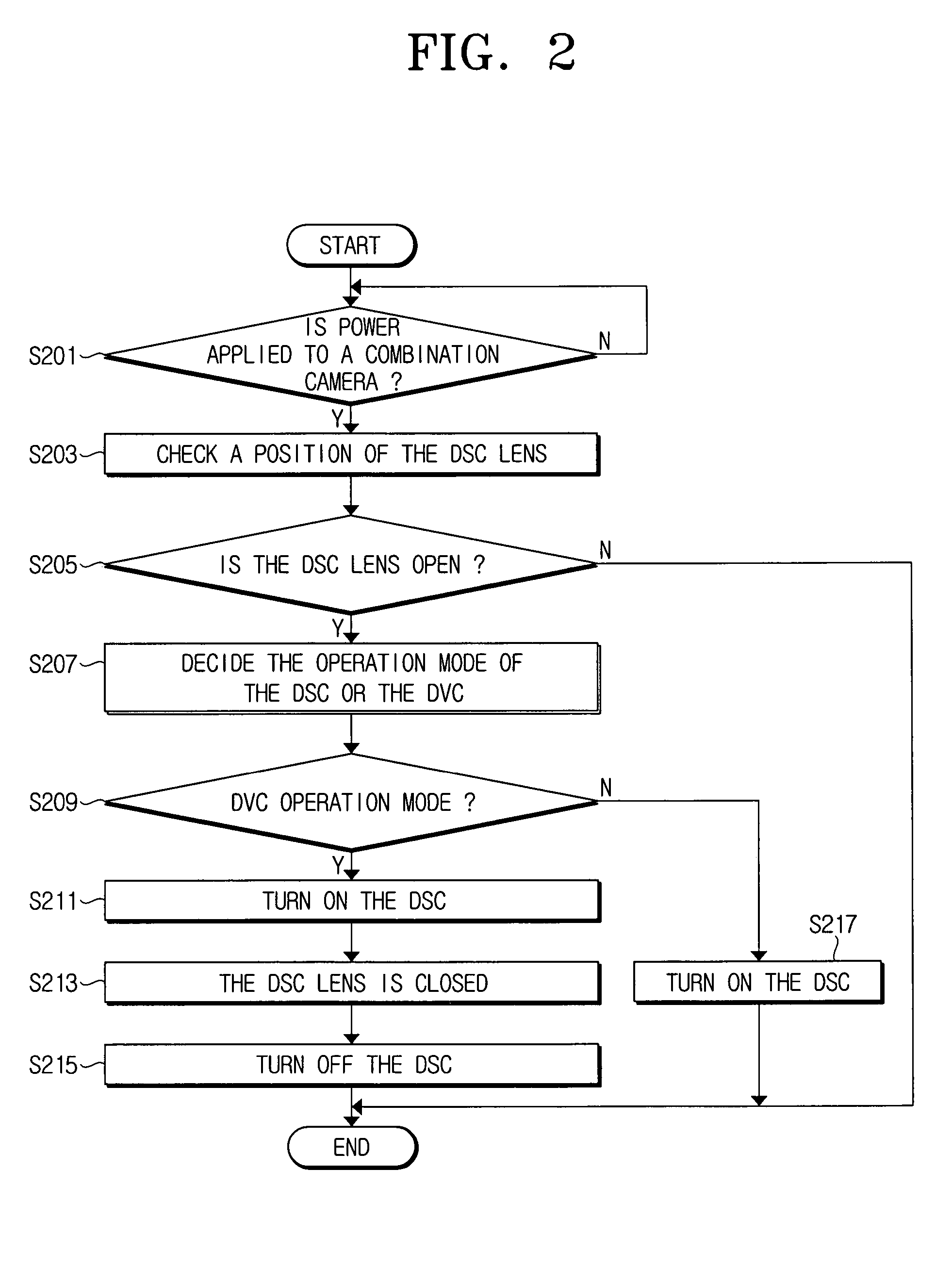
[0024]Therefore, the combination camera according to the present invention can efficiently control the DSC lens when the electric power is applied while in the DVC mode after the power is turned off when the DSC lens has been open.

Problems solved by technology

Such a DSC typically has a lens unit, a memory unit, a signal conversion unit, a display unit, and so forth, and is mainly used to capture still images due to the limited capacity of a recording medium for storing images.
However, the DVC can also be used to capture still images, but the captured still images are not as good in quality when compared to ones taken by the DSC.
Further, since the DVC has more functions and a more complicated structure than the DSC, the DVC can be relatively bulky in size and higher in price.
Thus, one currently has to purchase both products to use the respective functions of the DSC and DVC as stated above, which requires consumers to spend more money as well as creating inconveniences since one has to carry both products to use all of the functions of both the DSC and DVC.

Method used


Image

  • Combination camera and DSC lens control method using the same
  • Combination camera and DSC lens control method using the same
  • Combination camera and DSC lens control method using the same

Examples


Embodiment Construction

[0031]Hereinafter, a description will be made in detail of a combination camera and a DSC lens control method using the same with reference to the accompanying drawings. In the following description, same drawing reference numerals are used for the same elements even in different drawings. The matters defined in the description, such as detailed construction and element descriptions, are provided to assist in a comprehensive understanding of the invention. Also, functions or constructions well known to those skilled in the art are omitted for clarity and conciseness.

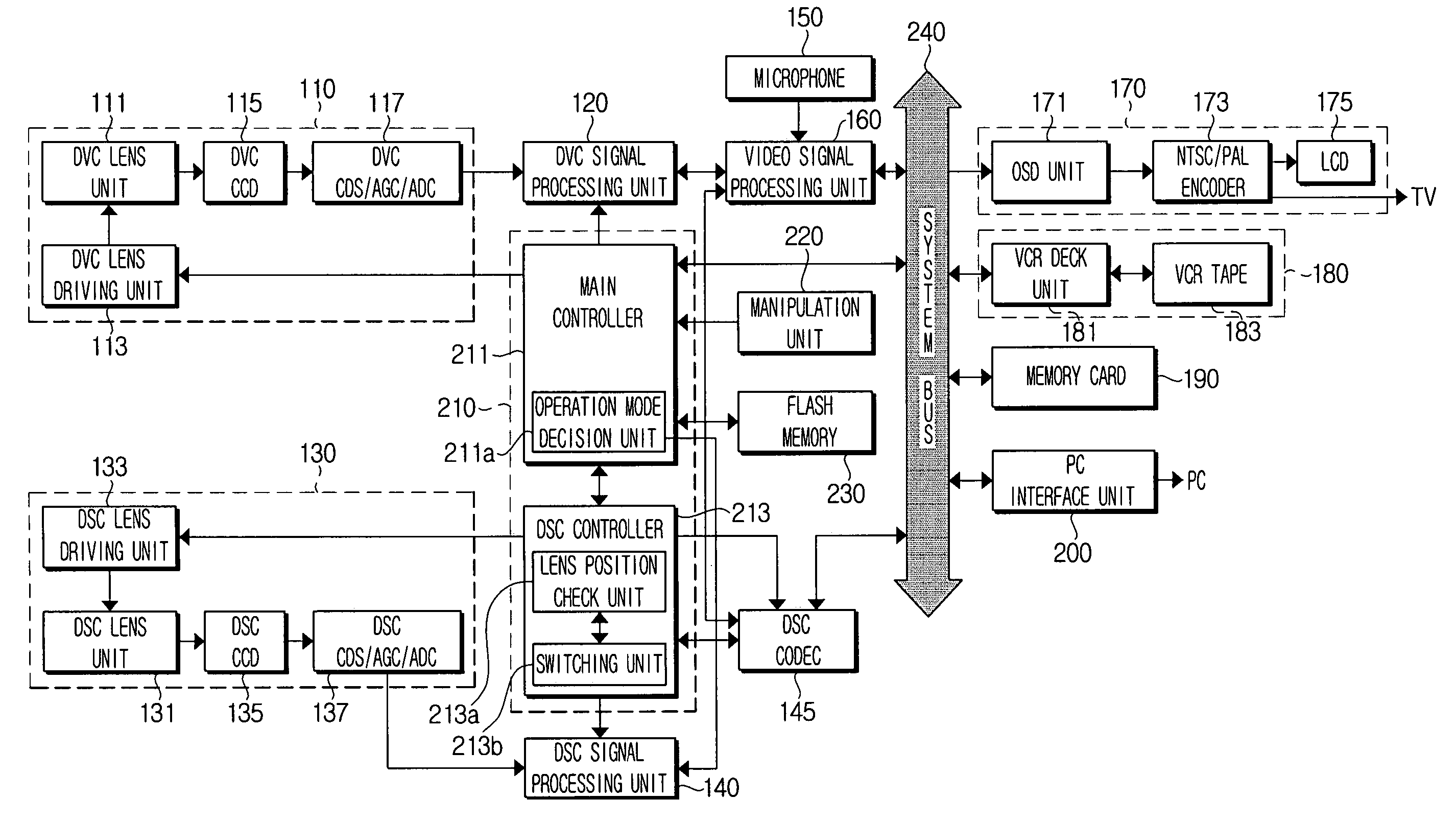
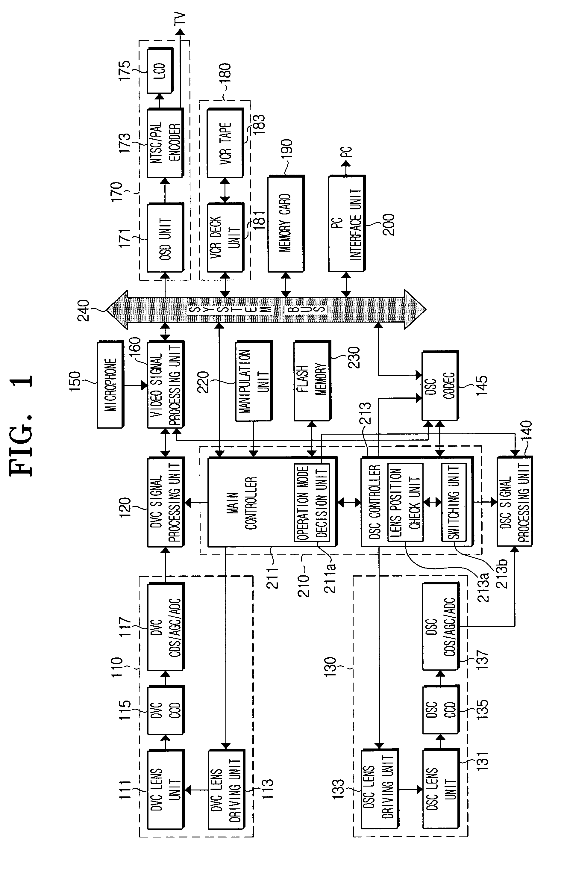
[0032]FIG. 1 is a block diagram for showing a combination camera according to an embodiment of the present invention. In FIG. 1, the combination camera has a digital video camera (DVC) picture-taking part 110, a DVC signal processing unit 120, a digital still camera (DSC) image-capturing part 130, a DSC signal processing unit 140, a DSC encoder / decoder (CODEC) unit 145, a microphone 150, a video signal processing unit 16...


PUM


Abstract

A combination camera and a DSC lens control method using the same, including a lens position check unit for checking a position of a DSC lens if electric power is applied, and a switching unit for switching the DSC lens to a closed state if the lens position check unit decides that the DSC lens is open. Thus, if the power is applied in the DVC mode after the combination camera is turned off when the DSC lens has been open, the combination camera can efficiently switch the DSC lens to the closed state to thereby eliminate a user's inconvenience of using the DVC picture-taking mode during the open state of the DSC lens, or the inconvenience of switching the mode to the DSC image-capturing mode to close the DSC lens and then switching the mode to the DVC picture-capturing mode for use.

Description

CROSS-REFERENCE TO RELATED APPLICATIONS[0001]This application claims the benefit under 35 U.S.C. §119(a) of Korean Patent Application No. 10-2004-0016055 filed on Mar. 10, 2004, the entire disclosure of which is hereby incorporated by reference.BACKGROUND OF THE INVENTION[0002]1. Field of the Invention[0003]The present invention relates to a combination camera and a digital still camera (DSC) lens control method using the same. More particularly, the present invention relates to a combination camera and a DSC lens control method capable of switching the DSC lens to a closed state when electric power cuts off while the DSC lens is open.[0004]2. Description of the Related Art[0005]In general, a digital still camera (DSC) converts an image focused through a lens into a digital signal, and stores the digital signal in a recording medium such as a hard disc, a memory card, and other such devices. That is, the digital still camera converts a taken image into a digital signal, stores the t...

Claims


Application Information

Patent Timeline
Patent Type & Authority Patents(United States)
IPC IPC(8): G03B7/26G03B17/48H04N5/225G03B17/02G03B17/16G03B19/07H04N5/232H04N101/00
CPCG03B17/16H04N5/23203H04N5/23245H04N23/66H04N23/667
Inventor KIM, KUIE-SUP
Owner SAMSUNG ELECTRONICS CO LTD
Why Eureka
Eureka Blog
Learn More