Analytical shell model forming apparatus

a technology of shell model and apparatus, which is applied in the field of numerical analysis system using a computer, can solve the problems of difficult to form a medial surface model suitable for analysis, and achieve the effect of shortening the time required for analysis and improving analysis precision

Inactive Publication Date: 2008-04-22
HITACHI LTD
View PDF5 Cites 8 Cited by
  • Summary
  • Abstract
  • Description
  • Claims
  • Application Information

AI Technical Summary

Benefits of technology

[0007]It is still another object of the present invention to improve the precision of analysis and shorten the time required for analysis by selecting a medial surface in accordance with analysis conditions.

Problems solved by technology

However, the analytical model forming method described in both JP-6-259505 and JP-A-2002-207777 does not consider that a medial surface model suitable for analysis is determined uniquely from a configuration model.
Therefore, there arises the problem that it is difficult to form a medial surface model suitable for analysis.

Method used


Image

  • Analytical shell model forming apparatus
  • Analytical shell model forming apparatus
  • Analytical shell model forming apparatus

Examples


Embodiment Construction

[0024]An analytical shell model forming apparatus according to an embodiment of the present invention will be described with reference to the accompanying drawing. In the description of this specification, an analytical shell model means a model having a defined analytical mesh, and configuration data before analytical mesh formation which data is used for forming the mesh is called a medial surface.

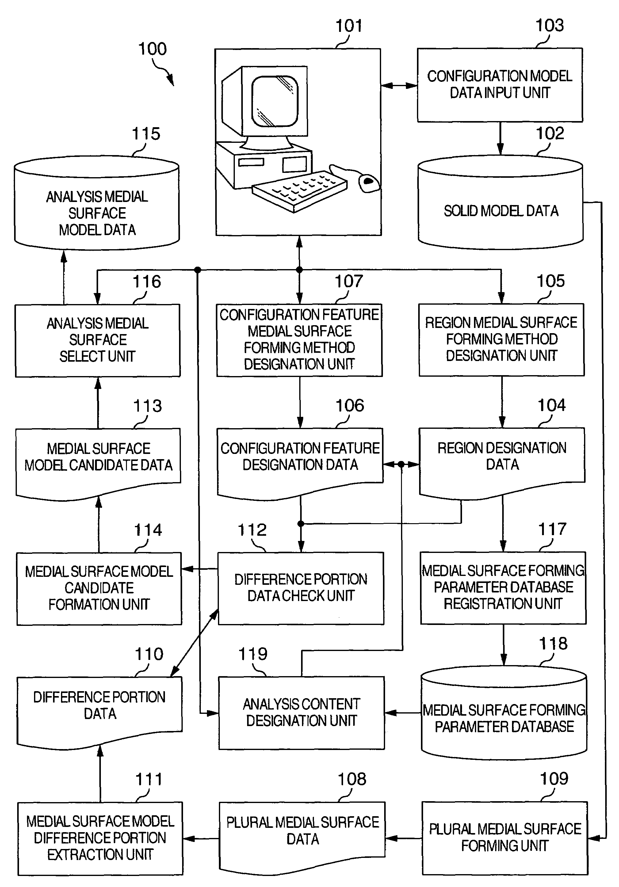
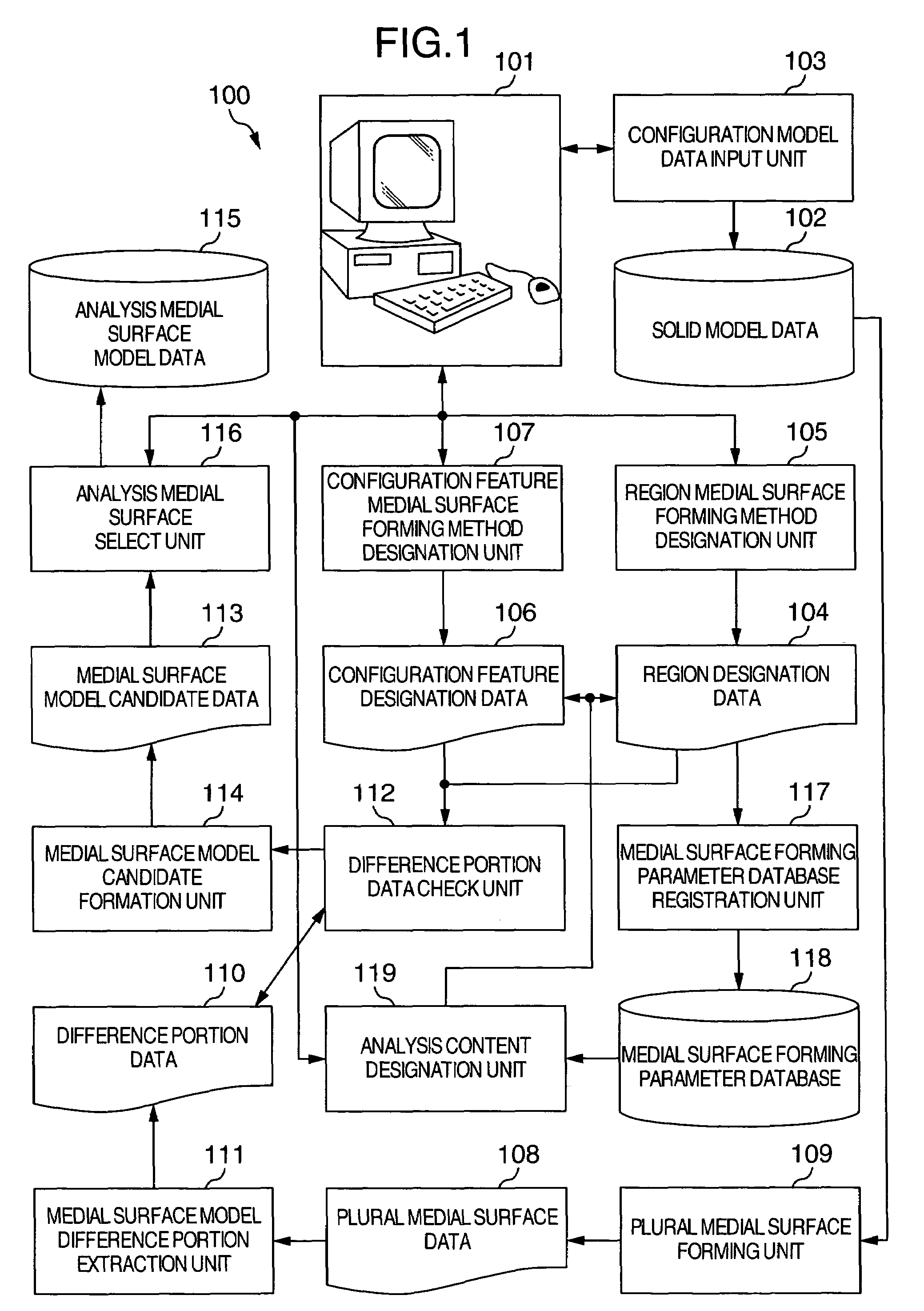
[0025]FIG. 1 is a diagram showing the system structure of an analytical shell model forming apparatus 100 according to an embodiment of the present invention. The analytical shell model forming apparatus 100 has an input / output unit 101 and a configuration model input unit 103. The input / output unit 101 has a keyboard, a pointing device and a display by which a user inputs and displays data. The configuration model input unit 103 registers an actual analysis target (solid model) having thickness as solid model data 102. The solid model input to the configuration model input unit 103 is d...


PUM


Abstract

An analytical shell model forming apparatus includes a medial surface forming unit for approximating a solid model to a plurality of shell models. An extracting unit compares a plurality of formed medial surface models and extracts difference portions. A model candidate forming unit forms a plurality of medial surface model candidates suitable for analysis by combining the extracted difference portions. A select unit selects a medial surface model matching boundary conditions, constraint conditions and the like from the plurality of model candidates. The selected medial surface model is presented to an operator as an analysis medial surface model.

Description

BACKGROUND OF THE INVENTION[0001]The present invention relates to a numerical analysis system using a computer, and more particularly to an apparatus for forming an analytical shell model from a solid model of a thin plate structure formed by a three-dimensional configuration modeler.[0002]An example of forming an analytical shell model from a solid model of a thin plate structure is described in JP-A-6-259505 and JP-A-2002-207777. According to an analytical model forming method described in JP-A-6-259505, even for configuration data expressed by boundary representation not having configuration features, in order to simplify a configuration with easy manipulations, a configuration model is converted into an internal data structure and geometrical features such as parallel and connection state are extracted from the configuration data. A configuration element of a portion of a simplified configuration and the type of simplification are input, a target configuration to be simplified i...

Claims


Application Information

Patent Timeline
Patent Type & Authority Patents(United States)
IPC IPC(8): G06F17/50G06F19/00G06T15/00G06T17/00G06T17/30
CPCG06T19/00G06T17/10G06F17/5018G06F30/23
Inventor ONODERA, MAKOTOHIRO, YOSHIMITSU
Owner HITACHI LTD
Why Eureka
Try Eureka