Gas-treatment devices

a technology of gas treatment device and gas filter, which is applied in the direction of respirator, inhalator, tracheal tube, etc., can solve the problem of relative bulkiness

Inactive Publication Date: 2008-04-29
SMITHS GRP PLC
View PDF12 Cites 27 Cited by
  • Summary
  • Abstract
  • Description
  • Claims
  • Application Information

AI Technical Summary

Problems solved by technology

This can be relatively bulky and is a particular problem where the patient is breathing unaided via a tracheostomy tube since it is preferable for this to be as unobtrusive as possible.

Method used


Image

  • Gas-treatment devices
  • Gas-treatment devices

Examples


Embodiment Construction

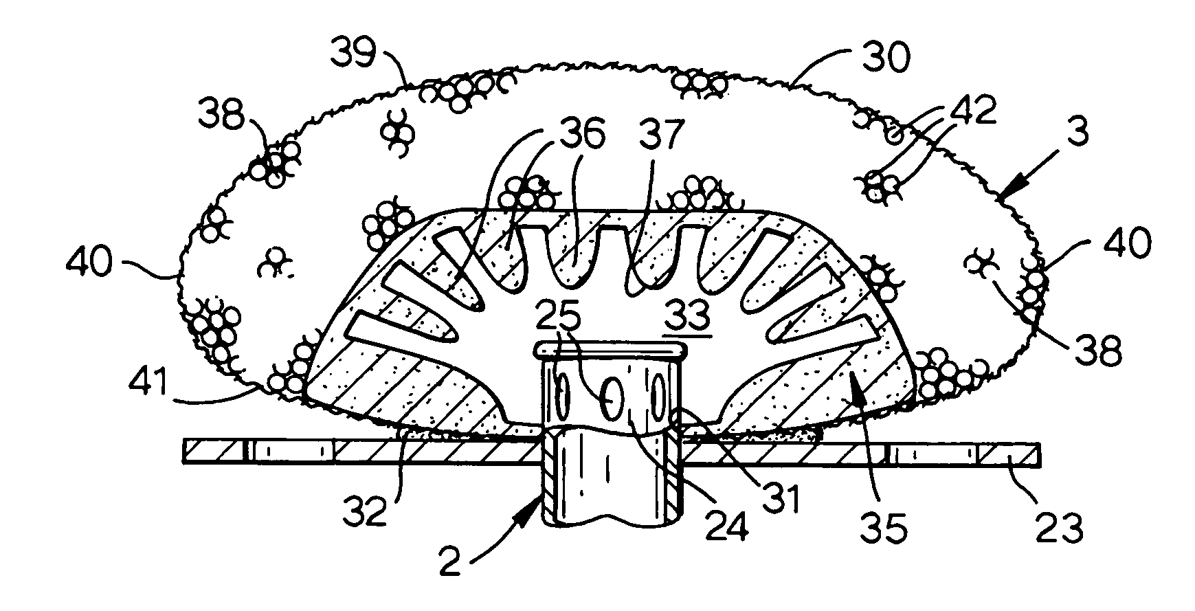
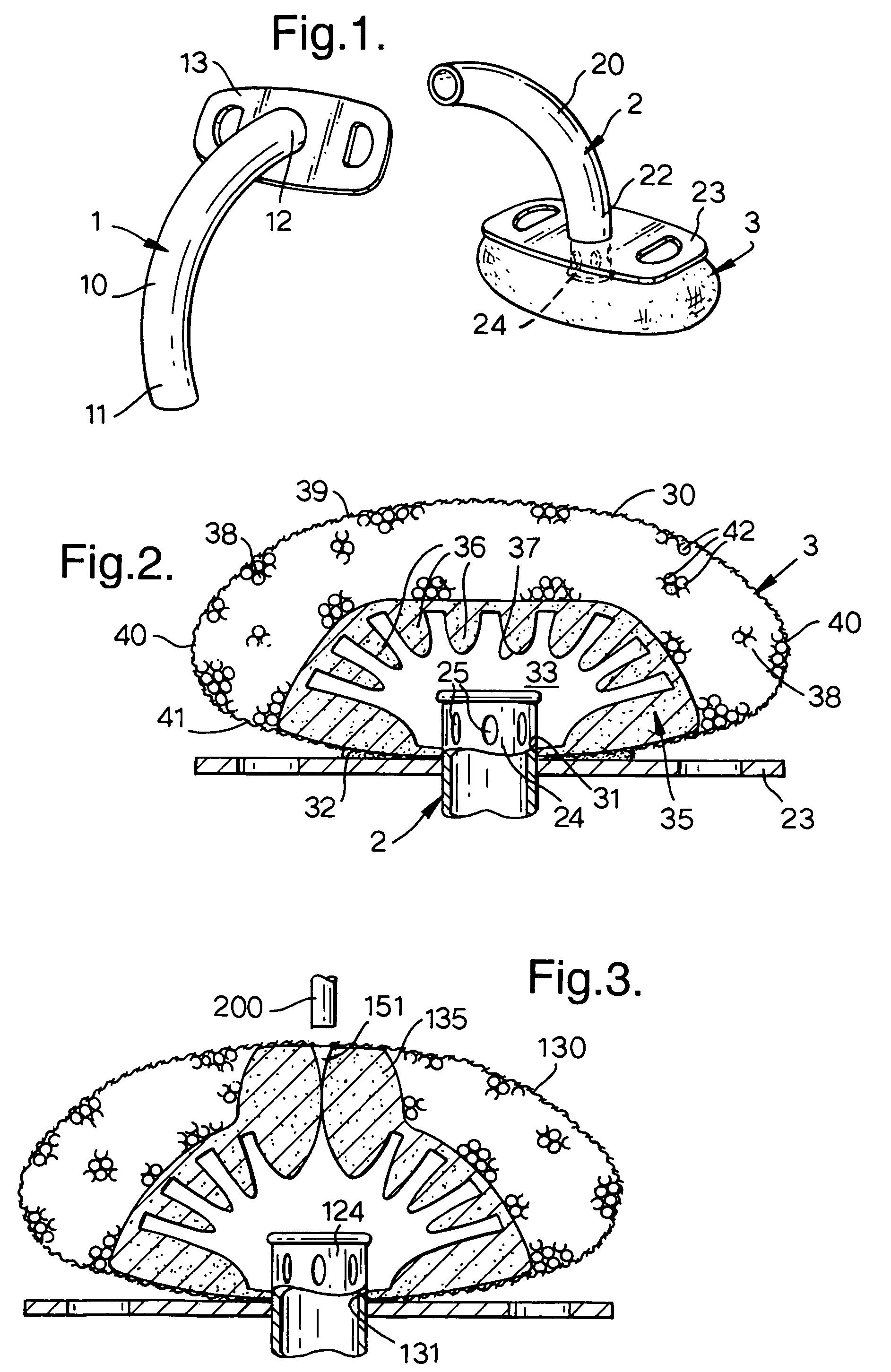
[0016]With reference first to FIGS. 1 and 2, the assembly comprises an outer, tracheostomy tube 1, a removable inner cannula or liner 2 and an HME gas-treatment device 3 connected to the machine end of the cannula. When inserted, the inner cannula 2 is considered to form a part of the tracheostomy tube 1.

[0017]The tracheostomy tube 1 is conventional having a shaft 10 curved to the anatomy of the patient so that, in use, its patient end 11 is directed caudally within the trachea. The machine end 12 of the tube 1 terminates flush with a laterally-extending flange 13 shaped to lie flat on the patient's skin to either side of the tracheostomy.

[0018]The cannula 2 has a shaft 20 curved to the same shape as the tracheostomy tube 1 and its external diameter is such that it is a close sliding fit within the tracheostomy tube. The cannula 2 also has a flange 23 at its machine end 22 of the same shape as the flange 13 of the tracheostomy tube so that the two flanges lie close to one another wh...


PUM


Abstract

An HME for a tracheostomy tube has a flexible outer housing of a gas-permeable material containing an HME element of discrete particles, granules or the like of a hygroscopic material. The particles are contained between the outer housing and an inner wall of a foam. The inner wall has a ciliated surface facing the end of the tube, which acts to distribute gas over the surface of the HME element. The HME is attached to a flange on an inner cannula by means of a removable adhesive. The HME may include a suction port through a self-closing aperture, which makes a wiping seal with a suction catheter inserted in the tube.

Description

BACKGROUND OF THE INVENTION[0001]This invention relates to gas-treatment devices.[0002]The invention is more particularly concerned with heat and moisture exchangers (HMEs) or the like for use with tracheostomy tubes.[0003]In normal breathing, inhaled air passes through the nose where it is warmed and moistened before passing to the trachea and bronchial passages. Where a patient breathes via a tracheal tube or laryngeal mask, gas is supplied directly to the trachea, by-passing the nose. The gas is, therefore, preferably warmed and moistened to prevent discomfort and damage to the lining of the trachea. This is often achieved by a heat and moisture exchange device or HME connected to the tracheal tube to receive both exhaled and inhaled gases. The HME has a moisture-absorbing element, such as of a treated paper or foam, that absorbs moisture in exhaled gases and transfers a major part of this to the inhaled gases. The element also warms inhaled gas in the same way. HMEs are sold by ...

Claims


Application Information

Patent Timeline
Patent Type & Authority Patents(United States)
IPC IPC(8): A62B7/00A61M16/04A61M16/10
CPCA61M16/047A61M16/1045A61M16/0427
Inventor PAGAN, ERIC
Owner SMITHS GRP PLC
Why Eureka
Try Eureka