Magnetic pulse welding of steel propshafts

a technology of magnetized pulse welding and propeller shaft, which is applied in the field of welding, can solve the problems of increasing the manufacturing cost and the weight of the drive shaft, the drive shaft is not stable, so as to achieve the effect of higher electrical conductivity

Active Publication Date: 2008-04-29
AMERICAN AXLE & MFG
View PDF18 Cites 8 Cited by
  • Summary
  • Abstract
  • Description
  • Claims
  • Application Information

AI Technical Summary

Problems solved by technology

Traditionally, joints have been attached to the tube using common welding techniques, which result in imbalance in the driveshaft.
The requisite balancing process increases the manufacturing cost and the weight of the driveshaft.
Although the welding method disclosed in U.S. Pat. No. 5,981,921 is acceptable for welding an aluminum tube to a steel joint, this method is unable to provide acceptable welds when welding components fabricated from a broader range of material types.

Method used


Image

  • Magnetic pulse welding of steel propshafts
  • Magnetic pulse welding of steel propshafts
  • Magnetic pulse welding of steel propshafts

Examples


Embodiment Construction

[0018]The following description of the preferred embodiments is merely exemplary in nature and is in no way intended to limit the invention, its application, or uses.

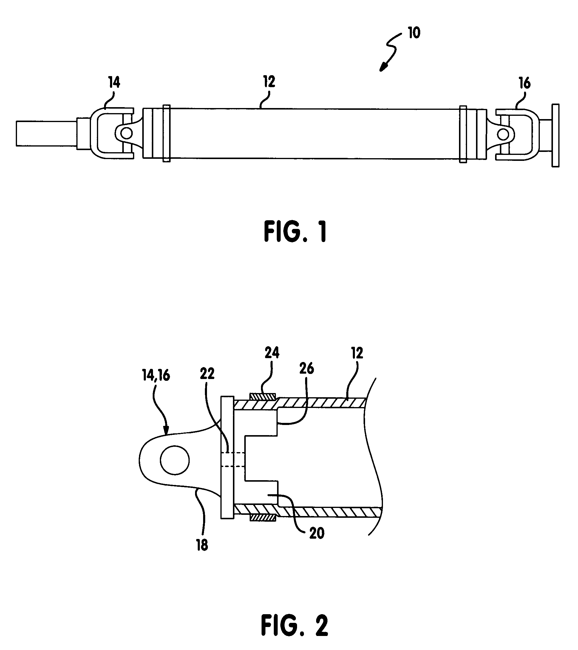
[0019]Referring now to FIG. 1, an exemplary propeller shaft 10 is illustrated. The propeller shaft 10 is of a type that is used to transfer drive torque from a transmission to a differential in a vehicle drivetrain. The propeller shaft 10 includes a tube 12, a slip joint assembly 14 and a flange or bolt joint assembly 16. It is appreciated that the propeller shaft 10 can include two slip joint assemblies 14 positioned at either end or two flange joint assemblies 16 at either end. It should also be noted that although the joint assemblies 14, 16 are illustrated as universal joints, they are merely exemplary in nature. It will be understood that other joint types, such as a constant velocity joint (CVJ), can substitute.

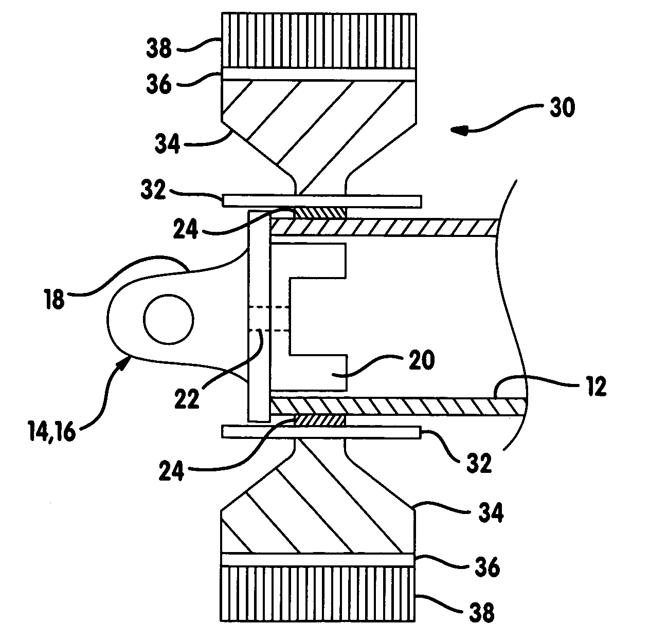
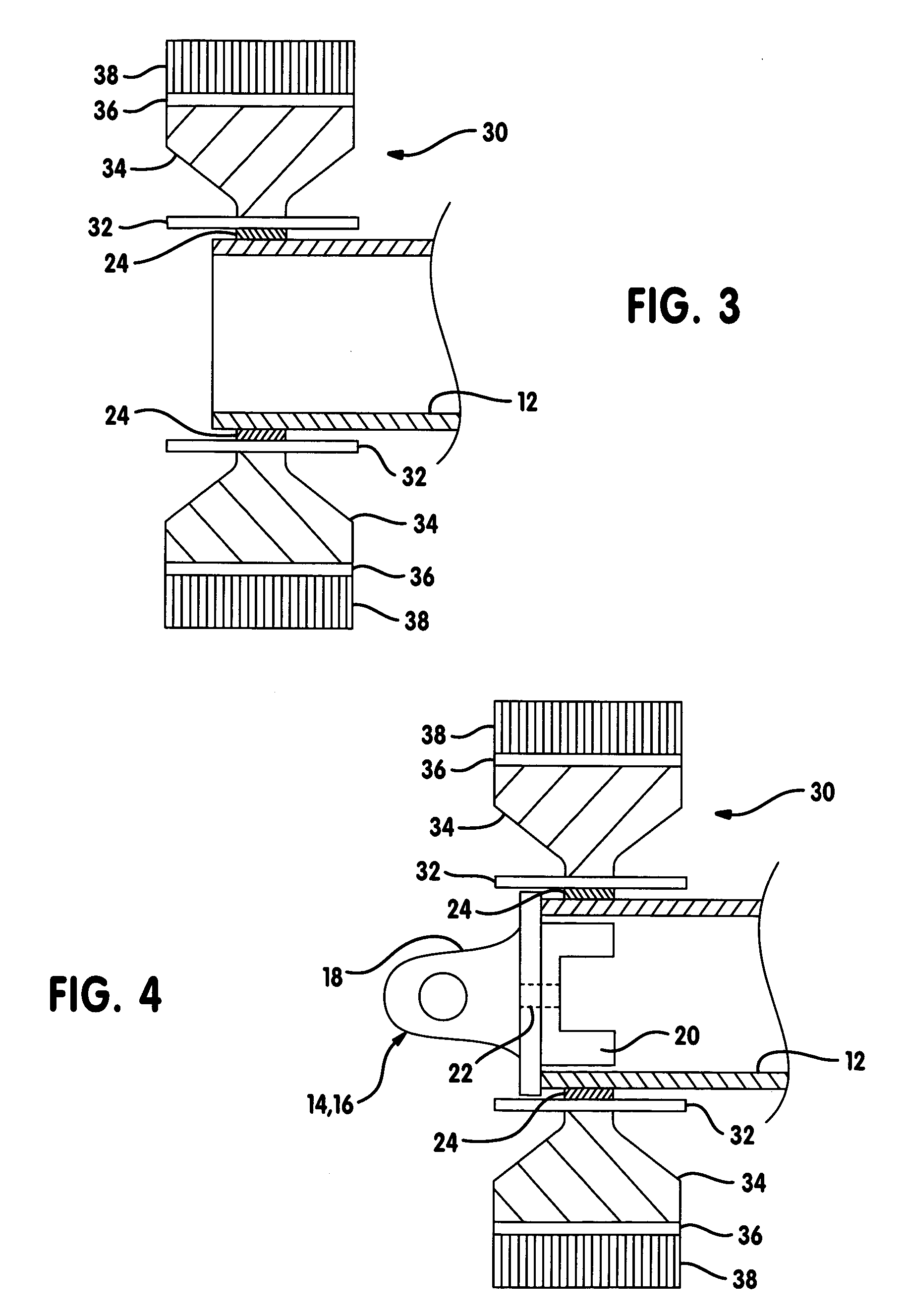
[0020]Referring now to FIG. 2, the tube 12 is welded to the joint assemblies 14,16 using the magnetic pu...


PUM

PropertyMeasurementUnit
electrical conductivityaaaaaaaaaa
electrically conductiveaaaaaaaaaa
magnetic fieldaaaaaaaaaa

Abstract

A method of magnetically welding an end fitting to a metal tube includes assembling a driver ring over an end of the tube and inserting a length of the end fitting into a bore of the tube. An overlap region of the tube, the driver ring and the cylinder are encompassed by an inductor assembly of a magnetic pulse welding apparatus and the tube is welded to the end fitting using the magnetic welding apparatus.

Description

FIELD OF THE INVENTION[0001]The present invention relates to welding, and more particularly to magnetic pulse welding of steel components of a propeller shaft of a vehicle.BACKGROUND OF THE INVENTION[0002]Vehicular driveshafts including, but not limited to, propeller shafts, transfer drive torque from one drivetrain component to another. For example, a driveshaft is commonly used to transfer drive torque from the output shafts of a transfer case to the differentials in the axle assemblies for driving the wheels of the motor vehicle. Driveshafts typically include a tube having angularly articulable joints disposed at either end. Exemplary joints include, but are not limited to, universal joints (UJ) and constant velocity joints (CVJ). The angularly articulable joints enable the driveshaft to accommodate changing relative angles between the drivetrain components while transferring drive torque therebetween.[0003]Traditionally, joints have been attached to the tube using common welding...

Claims


Application Information

Patent Timeline
Patent Type & Authority Patents(United States)
IPC IPC(8): B23K20/06B23K13/01
CPCB23K20/06B23K2201/006B23K2201/06B23K2101/006B23K2101/06
Inventor MOORE, JAMES B.
Owner AMERICAN AXLE & MFG
Why Eureka
Try Eureka