Injector

a technology of injector and sealing ring, which is applied in the direction of liquid fuel feeders, machines/engines, cable terminations, etc., can solve the problems of failure of the entire injection system and the inability to ensure the sealing function of the sealing ring, so as to achieve adequate flow cross section, reduce flow velocity, and increase the effect of relief grooves

Active Publication Date: 2008-04-29
ROBERT BOSCH GMBH
View PDF13 Cites 3 Cited by
  • Summary
  • Abstract
  • Description
  • Claims
  • Application Information

AI Technical Summary

Benefits of technology

[0007]The injector of the invention offers the advantage over the prior art that the existing short path through the recesses and relief grooves can be lengthened because of the offset of the recesses and relief grooves, and as a result the frictional forces which counteract an extrusion of the sealing ring material through the recesses and relief grooves can be increased considerably. In other words, the existing direct path is blocked, and a detour is created, which in combination with the small flow cross sections in the region of the detour, in other words between a recess and the adjacent relief groove, counteracts extrusion of the sealing ring material. The passage of the leak fuel flow continues to remain assured, and at the same time its flow velocity is advantageously reduced by the offset arrangement in the circumferential direction of the relief grooves and recesses. The injector of the invention furthermore has a support ring of sturdy construction, since the weakening zones formed by the relief grooves and the recesses do not coincide, and excessive motions in the region of the recesses, which are suspected to be one of the causes for extrusion of the sealing ring material, are avoided.
[0008]By the disposition of the recesses and relief grooves in accordance with the invention, the support ring has a material thickness in the region of the recesses that is greater, by the groove depth of the relief grooves, compared to the prior art. As a result, the lower edges of the recesses come closer to the housing wall of the injector, which in turn in this region results in smaller gap cross sections, which also counteract any extrusion.
[0009]In a preferred feature of the invention, it is provided that the relief grooves and the recesses are offset from one another in such a way that one recess each is located between two relief grooves adjacent to one another in the circumferential direction, while conversely, one relief groove each is disposed between two recesses adjacent to one another in the circumferential direction, in both cases preferably in the middle.
[0010]A further preferred feature of the invention provides that the support ring, as before, has a total of four recesses, disposed at a spacing of 90° in the circumferential direction, and four relief grooves, also disposed at a spacing of 90° in the circumferential direction, in order to assure an adequate flow cross section for the leak fuel flow, but that the relief grooves are disposed at an angular spacing of 45° from the recesses, and vice versa, in order to create the longest possible detours between adjacent relief grooves and recesses.
[0012]In a further preferred feature of the invention, the cross-sectional shape of the annular shoulder of the stepped bore and the cross-sectional shape of the support ring are advantageously adapted to one another in such a way that the support ring, between the recesses, rests with its outer circumferential edge essentially sealingly against a part, located above the annular shoulder, of the inner wall of the stepped bore and, between the relief grooves, rests with parts of its underside sealingly against the annular shoulder of the stepped bore. These parts of the underside that rest sealingly against the annular shoulder preferably border on the valve element and do not extend over the full width of the support ring, so that flow conduits extending radially outward from the sealingly contacting parts between the annular shoulder and the underside of the support ring in its circumferential direction remain open with a small flow cross section and establish a communication between the recesses and relief grooves. The flow conduits are preferably embodied in the underside of the support ring, but they may also be embodied as an annular groove in the annular shoulder. The flow cross section of these flow conduits is expediently essentially equivalent to that of the relief grooves and the recesses.

Problems solved by technology

With such an arrangement, however, an unwanted extrusion of the sealing ring material through the recesses and the relief grooves could occur, so that the sealing function of the sealing ring could no longer be assured and consequently failure of the entire injection system could be brought about.

Method used


Image

  • Injector
  • Injector
  • Injector

Examples


Embodiment Construction

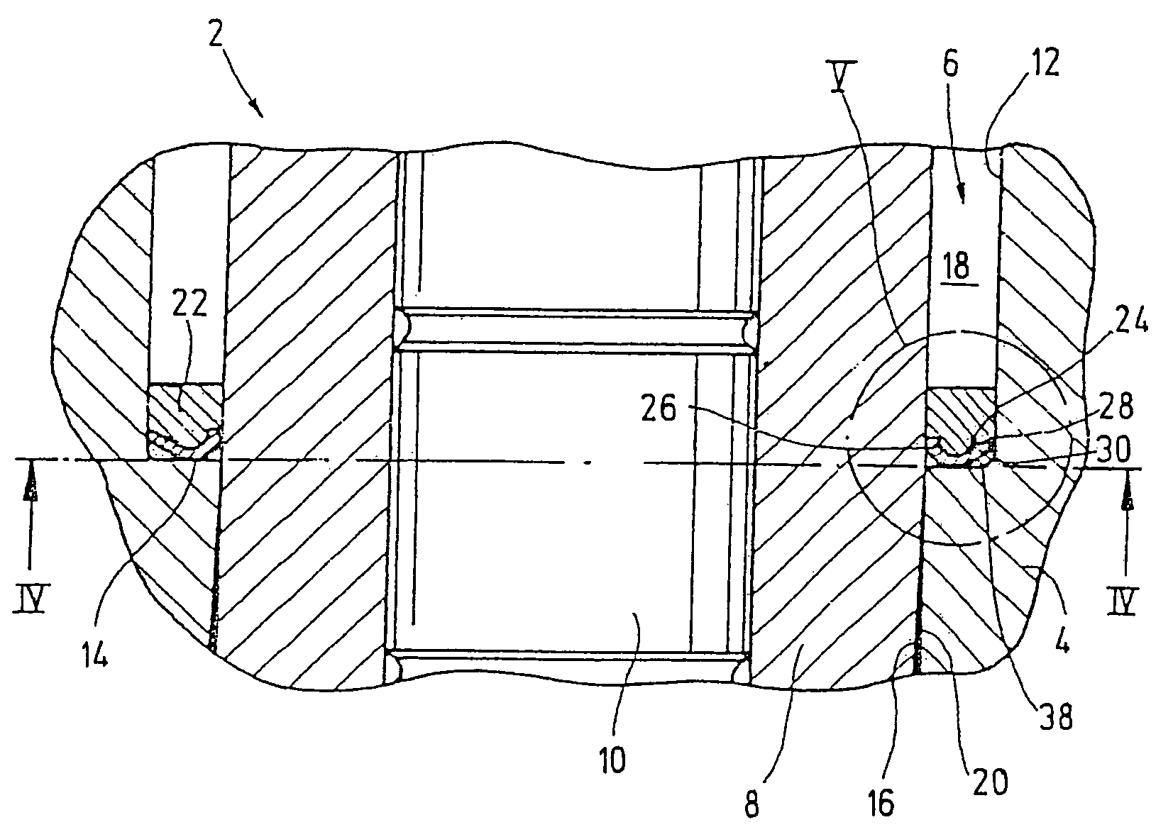
[0019]The injector 2, shown partially in FIG. 1 of the drawing, for a common rail injection system of an internal combustion engine serves to inject fuel from a central high-pressure reservoir, known as a common rail, into the combustion chambers of the engine.

[0020]The complete construction of such an injector has been described at length, for instance in German Patent Disclosures DE 196 19 523 A1 and DE 102 20 457 A1 and will therefore not be explained further at this point.

[0021]As best seen from FIG. 1, the injector 2 includes an injector housing 4 with a stepped bore 6. A valve element 8 is inserted into the stepped bore 6 and serves as a guide for a control rod 10, with which the opening and closing motions of a nozzle needle (not shown) of the injector 2 can be controlled.

[0022]The stepped bore 6 has a widened upper part 12, which is divided by an annular shoulder 14 from a narrowed lower part 16. The inside diameter of the widened upper part 12 of the stepped bore 6 is great...


PUM


Abstract

The invention relates to an injector for a common rail injection system of an internal combustion engine, having an injector housing, a valve element disposed in the injector housing, a sealing ring acting as a seal between a high-pressure region and a low-pressure region of the injector, and a support ring, disposed together with the sealing ring in an annular chamber between the injector housing and the valve element, for bracing the sealing ring, which is provided, in its underside remote from the sealing ring, with a plurality of relief grooves spaced apart in the circumferential direction and, in its outer circumferential edge, with a plurality of recesses spaced apart in the circumferential direction. The relief grooves and the recesses are disposed in offset fashion in the circumferential direction.

Description

CROSS-REFERENCE TO RELATED APPLICATION[0001]This application is a 35 USC 371 application of PCT / EP 2004 / 052659 filed on Oct. 25, 2004.BACKGROUND OF THE INVENTION[0002]1. Field of the Invention The invention relates to an injector for a common rail injection system of an internal combustion engine.[0003]2. Prior Art[0004]Common rail injection systems have a plurality of injectors, which under the control of an electronic motor controller are supplied with fuel by a high-pressure pump from a central high-pressure reservoir known as a common rail and inject the fuel into the combustion chambers of the engine.[0005]From German Patent Disclosure DE 100 20 870 A1, a common rail injector is already known whose injector housing contains a valve element that is inserted into a stepped bore in the injector housing and is sealed from the injector housing by a soft sealing ring, which serves as a seal between a high-pressure region and a low-pressure region of the injector. The sealing ring is ...

Claims


Application Information

Patent Timeline
Patent Type & Authority Patents(United States)
IPC IPC(8): F16J15/12F02M47/02F02M61/16F16J15/16
CPCF02M47/027F02M55/005F02M61/16F16J15/164F16J15/166F02M2200/16F02M47/02F16J15/16
Inventor HEDRICH, ADRIAN
Owner ROBERT BOSCH GMBH
Why Eureka
Try Eureka